22.3 Removing the XSCF BB Control Cable
22.3 Removing the XSCF BB Control Cable
This section describes the procedure for removing the XSCF BB control cable.
- Make a note of the XSCF BB control cable to be replaced.
Log in to the XSCF and execute the showstatus command or showlogs error command. Then, make a note of the ports connected to the XSCF BB control cable to be replaced. For details on the commands, see "8.2.2 Identifying a Fault."
- The underlined part in the error example below indicates that an error has been found in the XSCF BB control cable connected to BB#00 and BB#01.
| XSCF> showlogs error Date: Feb 12 20:23:38 JST 2016 Code: 80000080-00b00000b7ff00b001-01a100270000000000000000 Status: Alarm Occurred: Feb 12 20:23:38.337 JST 2016 FRU: /BB#00/XSCFU,/BB#00/SCF_CBL#0,/BB#01/XSCFU,* Msg: XSCF data synchronization failed |
From the above error message and "Appendix A Lists of Cable Connections in a Building Block Configuration," identify the port number at the other end of the connection of the target XSCF BB control cable.
In this example, "BB01-XSCF0" is the port number at the other end.
In this example, "BB01-XSCF0" is the port number at the other end.
- Write the port number on labels.
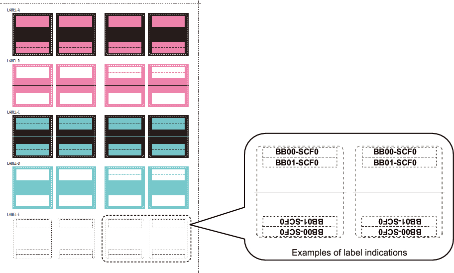
The replacement XSCF BB control cable comes with the labels shown in Figure 22-2. Write the connected port on these labels. For the XSCF BB control cable, use LABEL-E. As in the example shown in Figure 22-2, write the connected port number identified in step 1 on two labels.
|
Figure 22-2 Accompanying Labels and Examples of Label Indications
|
|
- Place the server in the cold state.
To perform maintenance after every SPARC M12-2S was placed in the cold state without using the maintenance menu, remove the power cords of every SPARC M12-2S. For details on handling power cords, see "9.8.2 Removing the Power Cords."
|
Figure 22-3 Removing the Power Cord
|
|
- Remove the XSCF BB control cable.
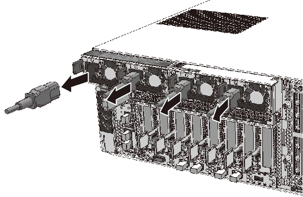
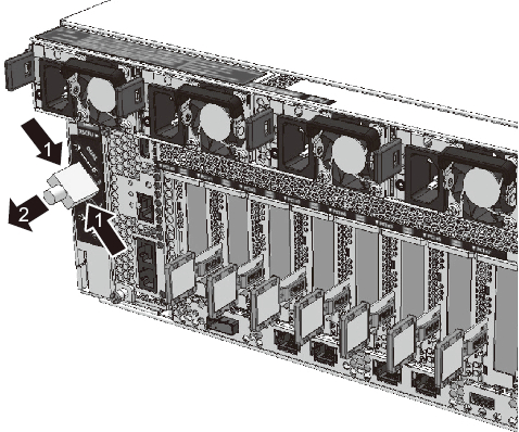
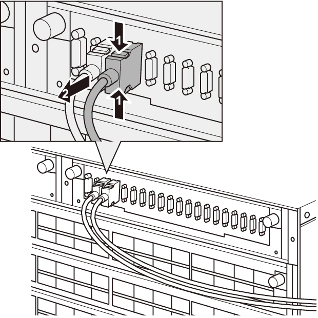
Pull out the XSCF BB control cable (in the direction of arrow 2 in Figure 22-4 and Figure 22-5) while pushing in the latches on both sides of the cable connector (in the directions of the arrows marked 1 in Figure 22-4 and Figure 22-5).
|
Figure 22-4 Removing the XSCF BB Control Cable (SPARC M12-2S)
|
|
|
Figure 22-5 Removing the XSCF BB Control Cable (Crossbar Box)
|
|
|

< Previous Page | Next Page >