18.4.3 Removing the PSUBP From the BPU
18.4.3 Removing the PSUBP From the BPU
This section describes the procedure for removing the PSUBP from the BPU.
| Note - The system shown in the illustrations provided herein is the SPARC M12-2S. Unless otherwise noted, the locations of the fixing screws and other details are common to the SPARC M12-2. |
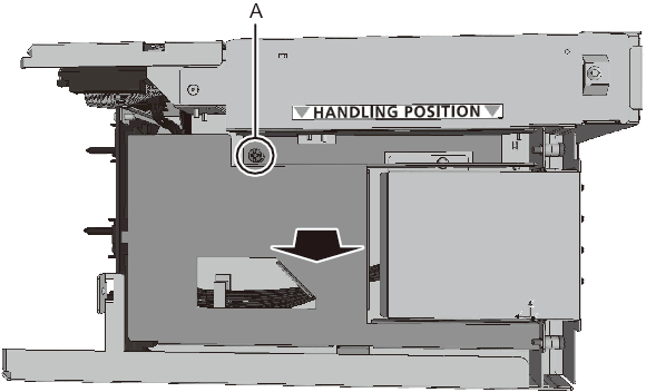
- Remove the connector cover.
To remove the connector cover, loosen the fixing screw of the connector cover (A in Figure 18-14) on the left side of the BPU and slide the connector cover toward you.
|
Figure 18-14 Removing the Connector Cover
|
|
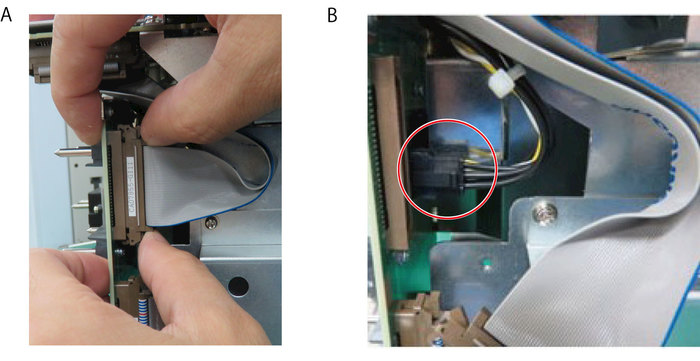
- Remove the PSUBP and BPU connectors.
There are two connectors that connect the BPU and PSUBP. First, close the latches on both sides of the connector (brown) shown in A of Figure 18-15, and remove the connector. Next, pull out the connector (black) shown in B of Figure 18-15 while pressing its latches.
|
Figure 18-15 Removing the Connectors
|
|
|

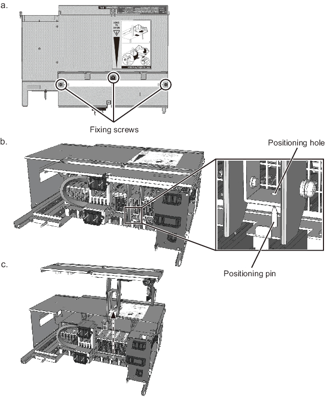
- Remove the PSUBP.
- a. Remove the three fixing screws. Store the removed fixing screws in a safe place.
- b. Keeping the PSUBP horizontal, lift it straight up until the positioning pin of the BPU is out of the positioning hole of the PSUBP.
- c. Remove the PSUBP from the BPU while taking care not to get caught on the connectors removed in step 2.
|
Figure 18-16 Removing the PSUBP
|
|
| Note - When you place the removed PSUBP on the workbench, make sure that its top side faces down. |
< Previous Page | Next Page >