18.5.1 Installing the PSUBP in the BPU
18.5.1 Installing the PSUBP in the BPU
This section describes the procedure for installing the PSUBP in the BPU.
| Note - The system shown in the illustrations provided herein is the SPARC M12-2S. Unless otherwise noted, the locations of the fixing screws and other details are common to the SPARC M12-2. |
- Install the PSUBP in the BPU.
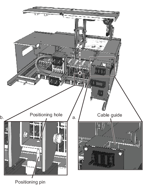
- a. Hold the PSUBP horizontal and route the cable through the cable guide of the BPU.
- b. While holding the PSUBP horizontal, lower it straight with the positioning hole of the PSUBP aligned with the positioning pin of the BPU. Install the PSUBP in the BPU. Make sure that the fixing screw holes of the PSUBP are aligned with those of the BPU.
|
Figure 18-17 Installing the PSUBP
|
|
|

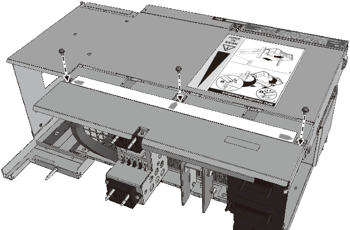
- Secure the PSUBP.
Tighten the three fixing screws to secure the PSUBP to the BPU.
|
Figure 18-18 Securing the PSUBP
|
|
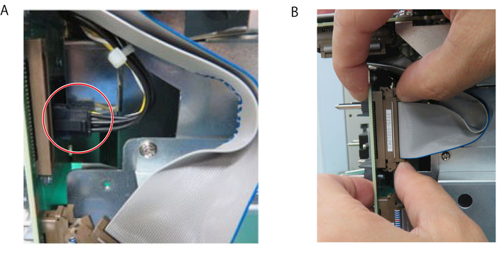
- Connect the PSUBP to the BPU.
There are two connectors that connect the PSUBP and BPU. Install the connector (black) shown in A of Figure 18-19 first and then the connector (brown) shown in B of Figure 18-19. To install the connector shown in B of Figure 18-19, insert it into the connector slot on the BPU side, with the latches closed, and then push it. Once the connector is secured, the latches open.
|
Figure 18-19 Connector Connection of the PSUBP and BPU
|
|
|
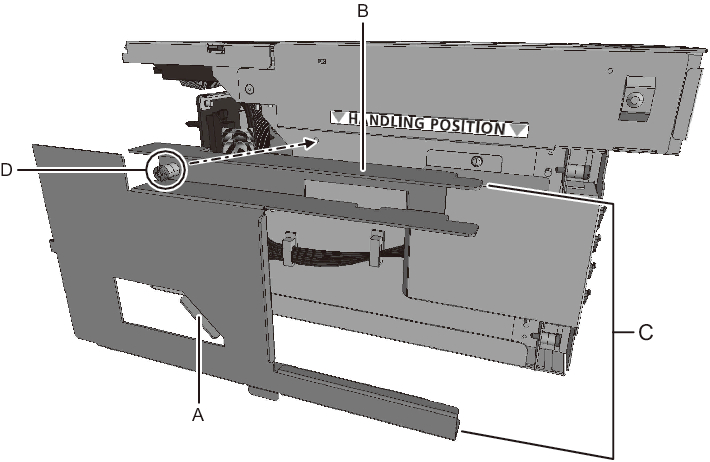
- Install the connector cover.
Hold the tab of the connector cover (A in Figure 18-20) to press the top surface (B in Figure 18-20) and the right ends (C in Figure 18-20) of the connector cover on to the BPU. Next, tighten the fixing screw (D in Figure 18-20) to secure the connector cover to the BPU.
|
Figure 18-20 Installing the Connector Cover
|
|
< Previous Page | Next Page >