19.4 Installing the Crossbar Cable
19.4 Installing the Crossbar Cable
This section describes the procedure for connecting the crossbar cable to XBUs.
- Affix labels to the crossbar cable.
Affix the labels filled out in step 2 in "19.3 Removing the Crossbar Cable" to the replacement crossbar cable.
For a crossbar cable (optical), affix them according to Figure 19-8. For a crossbar cable (electrical), affix them at the same locations as on the replaced cable.
|
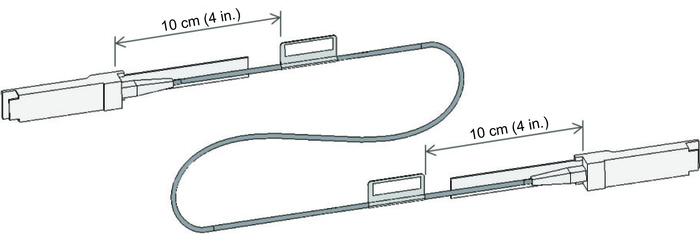
Figure 19-8 Label Affixing Positions on the Crossbar Cable
|
|
| Note - Affix a label 10 cm (4 in.) away from the crossbar cable connector. |
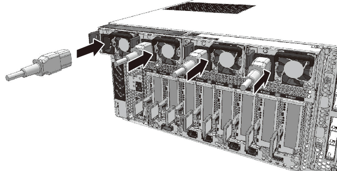
- Connect the crossbar cable to the XBUs.
Connect the crossbar cable to the XBU ports at the locations written on the labels.
There are four types of crossbar cables. Use only crossbar cables (optical) in maintenance/expansion of a SPARC M12-2S that uses crossbar cables (optical). Use only crossbar cables (electrical) in maintenance/expansion of a SPARC M12-2S that uses crossbar cables (electrical).
Connect crossbar cables of the same type to the same port numbers.
You can distinguish the type of crossbar cable by the pull-tab shape. (See Figure 19-9 and Figure 19-10.)
|
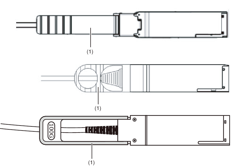
Figure 19-9 Crossbar Cable (Optical) Shapes and Pull-Tabs
|
|
| Number in Figure | Description |
|---|---|
| 1 | Pull-tab |
|
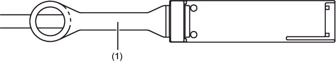
Figure 19-10 Crossbar Cable (Electrical) Shape and Pull-Tab
|
|
| Number in Figure | Description |
|---|---|
| 1 | Pull-tab |
|

| Note - On the crossbar box side, you may connect the crossbar cables with the power on. |
- Bundle the crossbar cables.
Bundle the crossbar cables with the hook-and-loop fastener. - Confirm that the crossbar cables are correctly and firmly connected.
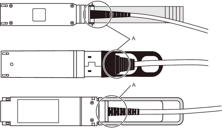
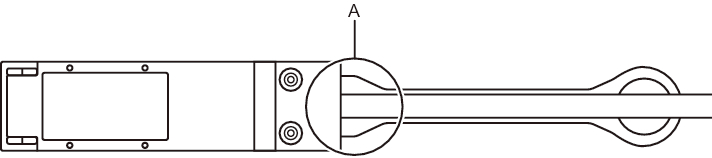
With the crossbar cables connected to their ports, push in each cable while holding the joint (A in Figure 19-11 and Figure 19-12) at the base of the crossbar cable connector.
|
|
Figure 19-11 Part to Hold When Checking a Crossbar Cable (Optical) Connection
|
|
|
Figure 19-12 Part to Hold When Checking a Crossbar Cable (Electrical) Connection
|
|
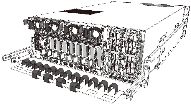
- Return the cable support to the original position.
Return the cable support to the pre-maintenance position.
|
Figure 19-13 Returning to the Pre-Maintenance State
|
|
- Place the server in the hot state.
To perform maintenance after every SPARC M12-2S was placed in the cold state without using the maintenance menu, install the power cords of every SPARC M12-2S. For details on installing the power cord on the server, see "10.1.1 Installing a Power Cord."
|
Figure 19-14 Installing the Power Cord
|
|
< Previous Page | Next Page >