2.3 Understanding the OPNL Functions
2.3 Understanding the OPNL Functions
This section describes the functions of the OPNL mounted on the SPARC M12-2/M12-2S.
The OPNL is mounted at the lower right as seen from the front of the panel (see Figure 2-1).
The OPNL provides the display and control functions of the system. The field engineer and system administrator can control the operation mode or start/stop of the system while checking the LEDs indicating the system operation status.
| Note - In a building block configuration, the functions of the Mode switch and POWER switch are disabled on the OPNL except for the master XSCF. |
| Note - In a building block configuration where the crossbar boxes are connected, all the OPNL functions are enabled only for the OPNL of the crossbar box used as the master XSCF. |
|
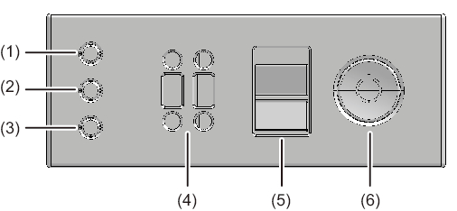
Figure 2-8 OPNL
|
|
| Location No. | LED/Switch |
|---|---|
| 1 | POWER LED |
| 2 | XSCF STANDBY LED |
| 3 | CHECK LED |
| 4 | BB-ID switch (only on SPARC M12-2S) |
| 5 | Mode switch |
| 6 | Power switch |
Table 2-9 lists the functions of the OPNL LEDs and switches.
| OPNL LED/Switch |
Functional Overview |
|---|---|
| POWER LED | Indicates the run/stop status of the SPARC M12-2/M12-2S. |
| XSCF STANDBY LED | Indicates the XSCF status of the system. |
| CHECK LED | Indicates any abnormality of the SPARC M12-2/M12-2S. |
| BB-ID switch (*1) | Sets the identifier of the SPARC M12-2S. |
| Mode switch (*2)(*3) | Sets the system operation mode. |
| Power switch (*2) | Starts/Stops the system. |
| *1 The SPARC M12-2 has no BB-ID switch. The BB-ID is fixed to 0. *2 In the building block configuration, this switch can be operated only with the SPARC M12-2S of the master XSCF. *3 Set the same operation mode for both the SPARC M12-2S of the master XSCF and that of the standby XSCF. If the operation mode is different, an asterisk (*) is displayed next to the unit names in the output result of the showhardconf or showstatus command. |
|
< Previous Page | Next Page >