17.2 Locations of the CMU and Memory
17.2 Locations of the CMU and Memory
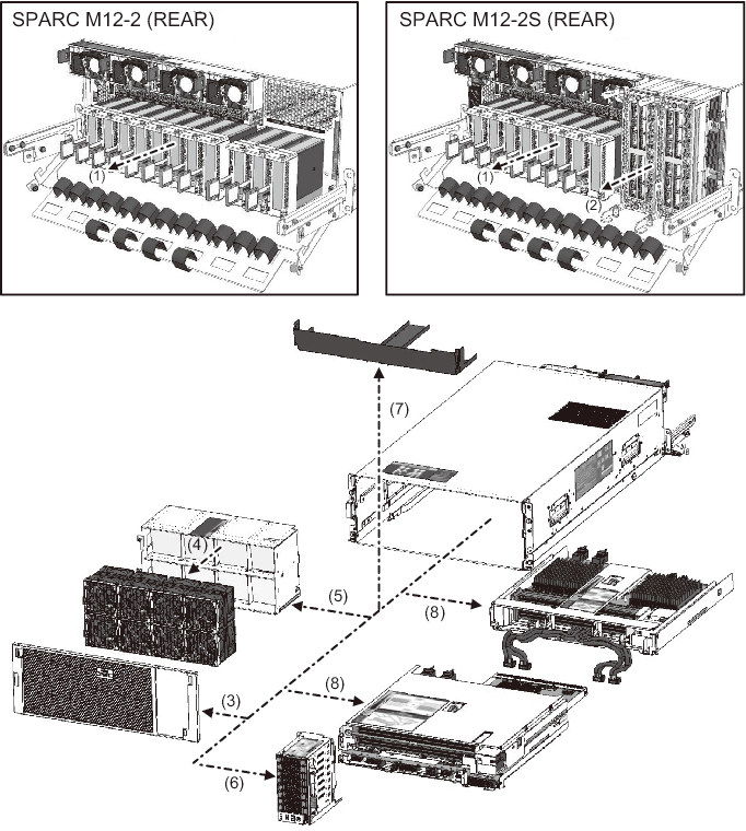
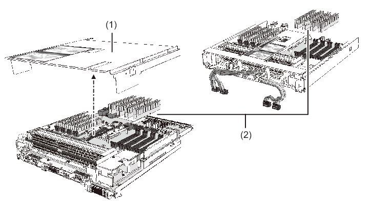
Figure 17-1 and Figure 17-2 show the mounting locations of the CMU and memory. The numbers in the figure represent the order in which the units are to be removed.
|
Figure 17-1 Location of the CMU
|
|
| Location No. | Unit |
|---|---|
| 1 | PCIe card (*1) |
| 2 | XBU (*2) |
| 3 | Front cover |
| 4 | FANU |
| 5 | FANBPU |
| 6 | HDDBPU |
| 7 | CMU filler unit (*3) |
| 8 | CMU |
| *1 The SPARC M12-2 houses 11 cassettes, and the SPARC M12-2S houses 8 cassettes. *2 This unit is mounted only in the SPARC M12-2S. *3 This unit is mounted in a system that has only the CMUL when purchased. |
|
|
Figure 17-2 Locations of Memory
|
|
| Location No. | Unit |
|---|---|
| 1 | CMUL top cover |
| 2 | Memory |
< Previous Page | Next Page >