18.5.3 Restoring the Server
18.5.3 Restoring the Server
This section describes the procedure for restoring the server after performing maintenance on the BPU.
- Install the CMUL.
Insert the CMUL into the server, with the CMUL levers open. Then, tighten the two fixing screws to secure the CMUL to the server. For details, see "17.5.2 Installing the CMU."
|
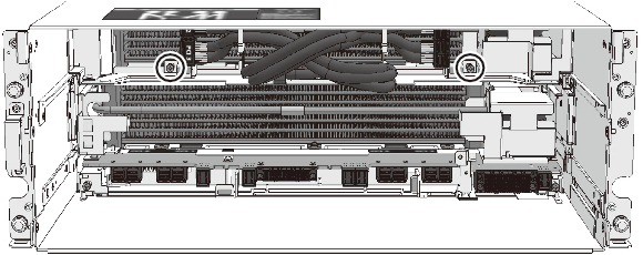
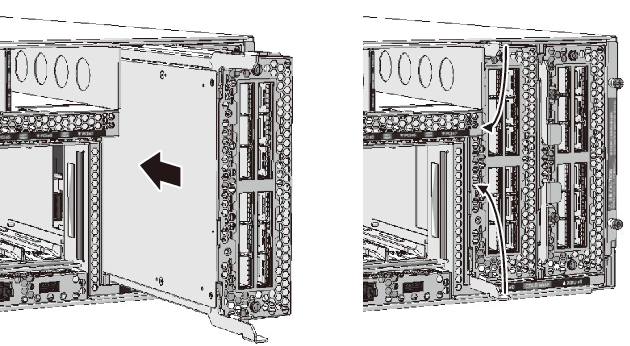
Figure 18-23 Connecting the CMUL to the BPU
|

|
- Secure the CMUU.
- Insert the CMUU into the server, with the CMUU levers open. Then, tighten the two fixing screws to secure the CMUU to the server. For details, see "17.5.2 Installing the CMU."
When the CMUU is not mounted, this step is not necessary. Proceed to step 4.
|
Figure 18-24 Connecting the CMUU to the BPU
|
|
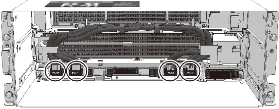
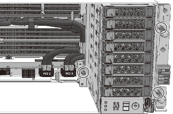
- Connect the PCIe cables.
Remove the PCIe cables from the cable clamps and connect them to the CMUL. For details, see step 4 in "17.5.2 Installing the CMU."
|
Figure 18-25 Connecting the PCIe Cables
|
|
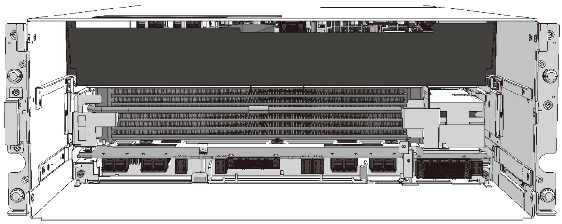
- Install the CMU filler unit.
| Note - If the CMUU is mounted or the CMU filler unit is not mounted, this step is not necessary. Proceed to step 5. |
- Install the CMU filler unit. For details, see step 5 in "17.5.2 Installing the CMU."
|
Figure 18-26 Securing the Filler Unit
|
|
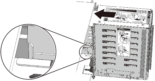
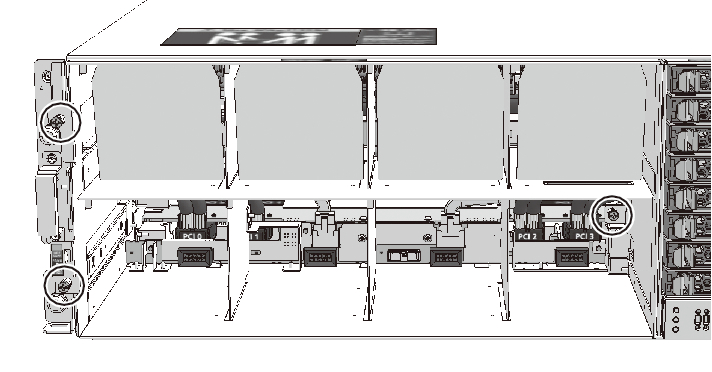
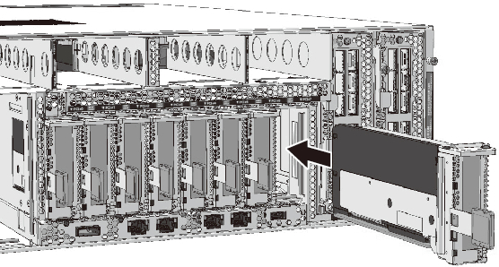
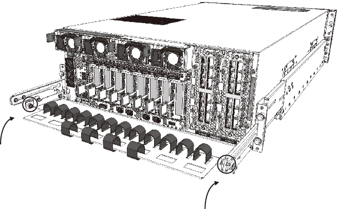
- Install the HDDBPU.
Align the positioning guide of the HDDBPU with the guide on the front right side inside the server. Then, install the HDDBPU in the server and tighten the fixing screws to secure it. For details, see "16.4.2 Installing the HDDBPU in the Server."
|
Figure 18-27 Connecting the CMU While Keeping It Aligned with the Positioning Guide of the HDDBPU
|
|
|
Figure 18-28 Securing the HDDBPU
|
|
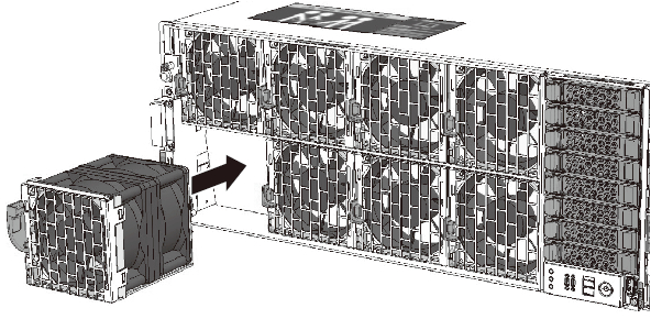
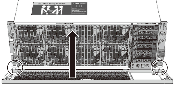
- Install the FANBPU and FANUs.
Install the FANBPU in the server, and then install the FANUs. For details, see "14.4.1 Installing the FANBPU" and "14.4.2 Installing a FANU."
|
Figure 18-29 Securing the FANBPU
|
|
|
Figure 18-30 Installing the FANUs
|
|
- Install the front cover.
|
Figure 18-31 Installing the Front Cover
|
|
- Install the XBU.
- Install the XBU in the server, and secure it to the server by tightening the fixing screws. For details, see "20.4 Installing an XBU."
Note that, when you use the SPARC M12-2, this step is not necessary. Proceed to step 10.
|
Figure 18-32 Installing the XBU
|
|
- Connect the crossbar cables.
- Connect the crossbar cables to the XBU. For details, see "19.4 Installing the Crossbar Cable."
|

|
| Note - The destination port for the XBU is described on a label affixed to the crossbar cable. Check the label first and connect the cable to the port of the XBU. For crossbar cable connection destinations, see "4.3 Connecting Crossbar Cables" in the Fujitsu SPARC M12-2S Installation Guide. |
- Install the PCICS.
Install the PCICS in the server, and then secure the PCICS. For details, see "12.4 Installing a PCIe Card."
|
Figure 18-33 Installing the PCICS
|
|
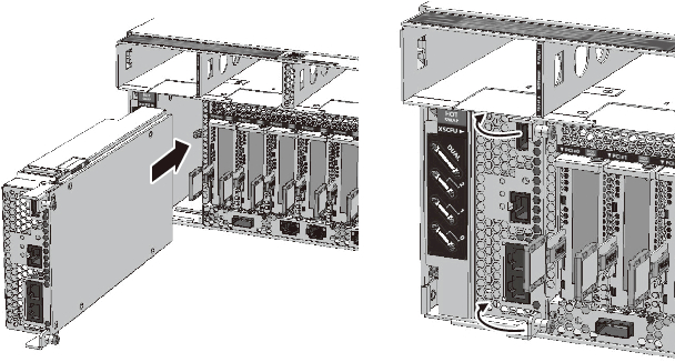
- Install the XSCFU.
Install the XSCFU in the server, and secure it by tightening the two fixing screws. For details, see "11.6 Installing the XSCFU."
|
Figure 18-34 Installing the XSCFU
|
|
- Install the PSUs.
Install the PSUs to the server. Do not install the power cords yet. For details, see "13.4 Installing a PSU."
|
Figure 18-35 Installing the PSUs
|
|
| Note - Install all of the four PSUs in the server. |
- Connect the cables.
Connect the cables to the XSCFU, PCIe cards, and on-board I/Os. For the SPARC M12-2S in a multiple-BB configuration, connect the XSCF DUAL control cable and XSCF BB control cable.
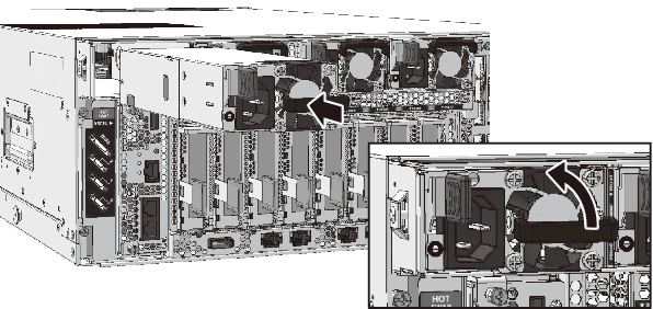
- Secure the cable support.
Return the cable support to the original position and tighten the two screws to secure it.
|
Figure 18-36 Securing the Cable Support
|
|
- Start the XSCF.
Connect the power cords to the PSUs and start the XSCF. XSCF startup completes when the READY LED of the XSCFU is lit. For details, see "XSCFU" in "2.4.3 LEDs of Each Unit." After the XSCF starts up, perform the work required after maintenance such as restoring the logical domain.
< Previous Page | Next Page >