2.2.1 Memory Installation Rules
2.2.1 Memory Installation Rules
Install memory according to the following rules.
- Install the memory in units of eight modules.
- All of the memory installed in a unit of eight modules must be of the same capacity, rank, and type.
- Within the same system, you can install memory modules of different capacities. However, the memory installed in the DIMM slots under each CMU (CMUL or CMUU) must be a combination of memory modules shown in Table 2-1 and Table 2-2.
- When installing memory modules for the CMU in the SPARC M12-2/M12-2S (16 memory slots), install memory group A and then memory group B.
- When installing memory modules of different capacities for the CMU in the SPARC M12-2/M12-2S (24 memory slots), install memory group A, memory group B, and memory group C in this order, from largest to smallest capacity.
- For the SPARC M12-2S in a multiple-BB configuration, install at least one set of memory modules (eight dual inline memory modules (DIMMs)) in each chassis.
- To mount a 64 GB DIMM, see "Notes on Memory" in the latest version of the Fujitsu SPARC M12 Product Notes.
| Memory Group | ||
|---|---|---|
| A | B | |
| (a) 64 GB memory module | 8 GB DIMM x 8 |
- |
8 GB DIMM x 8 |
8 GB DIMM x 8 |
|
| (b) 128 GB memory module | 16 GB DIMM x 8 |
- |
16 GB DIMM x 8 |
16 GB DIMM x 8 |
|
| (c) 256 GB memory module | 32 GB DIMM x 8 |
- |
32 GB DIMM x 8 |
32 GB DIMM x 8 |
|
| (d) 512 GB memory module | 64 GB DIMM x 8 |
- |
64 GB DIMM x 8 |
64 GB DIMM x 8 |
|
| Mix of (a) and (b) | 8 GB DIMM x 8 |
16 GB DIMM x 8 |
16 GB DIMM x 8 |
8 GB DIMM x 8 |
|
| Mix of (a) and (c) | 8 GB DIMM x 8 |
32 GB DIMM x 8 |
32 GB DIMM x 8 |
8 GB DIMM x 8 |
|
| Mix of (b) and (c) | 16 GB DIMM x 8 |
32 GB DIMM x 8 |
32 GB DIMM x 8 |
16 GB DIMM x 8 |
|
| Mix of (c) and (d) | 32 GB DIMM x 8 |
64 GB DIMM x 8 |
64 GB DIMM x 8 |
32 GB DIMM x 8 |
|
- : Empty |
||
| Memory Group | |||
|---|---|---|---|
| A | B | C | |
| (b) 128 GB memory module | 16 GB DIMM x 8 |
- | - |
16 GB DIMM x 8 |
16 GB DIMM x 8 |
- | |
16 GB DIMM x 8 |
16 GB DIMM x 8 |
16 GB DIMM x 8 |
|
| (c) 256 GB memory module | 32 GB DIMM x 8 |
- | - |
32 GB DIMM x 8 |
32 GB DIMM x 8 |
- | |
32 GB DIMM x 8 |
32 GB DIMM x 8 |
32 GB DIMM x 8 |
|
| (d) 512 GB memory module | 64 GB DIMM x 8 |
- | - |
64 GB DIMM x 8 |
64 GB DIMM x 8 |
- | |
64 GB DIMM x 8 |
64 GB DIMM x 8 |
64 GB DIMM x 8 |
|
| Mix of (b) and (c) | 32 GB DIMM x 8 |
16 GB DIMM x 8 |
- |
32 GB DIMM x 8 |
16 GB DIMM x 8 |
16 GB DIMM x 8 |
|
32 GB DIMM x 8 |
32 GB DIMM x 8 |
16 GB DIMM x 8 |
|
| Mix of (c) and (d) | 64 GB DIMM x 8 |
32 GB DIMM x 8 |
- |
64 GB DIMM x 8 |
32 GB DIMM x 8 |
32 GB DIMM x 8 |
|
64 GB DIMM x 8 |
64 GB DIMM x 8 |
32 GB DIMM x 8 |
|
-: Empty |
|||
When configuring memory mirroring
In addition to the above installation rules, observe the rules below as well when you configure memory mirroring.
- Configure a mirroring pair as a unit of eight modules by combining two sets of memory, with four modules per set. (See Figure 2-5 and Figure 2-6.)
- For memory groups A and B of each CPU in the SPARC M12-2/M12-2S (16 memory slots), install memory modules that are all of the same capacity and rank.
- For memory groups A, B, and C of each CPU in the SPARC M12-2/M12-2S (24 memory slots), install memory modules that are all of the same capacity and rank.
- Set the memory mirror mode for each CPU or CMU.
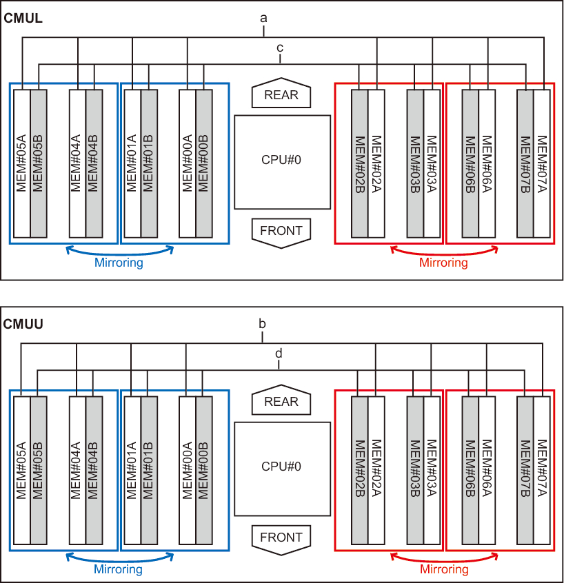
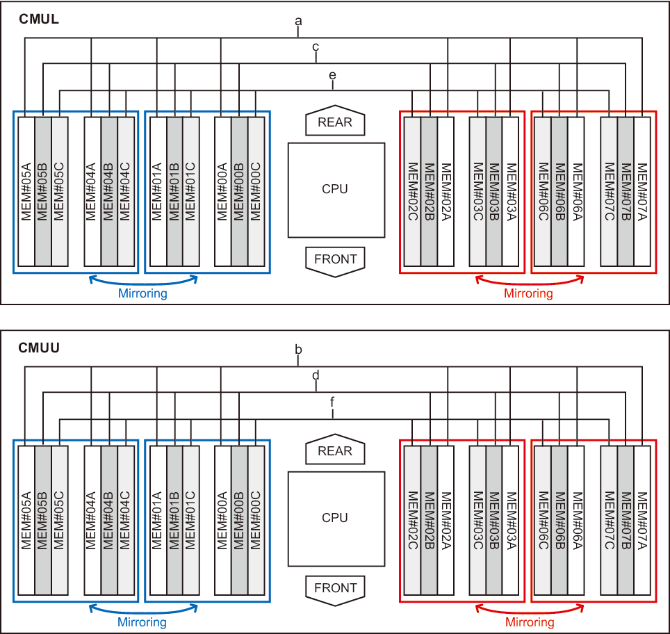
Memory Installation Locations and Memory Installation Patterns
Figure 2-5 and Figure 2-6 show all the memory installation locations, where a to f indicate memory installed in units of eight modules. Also, Table 2-3, Table 2-4, Table 2-5, Table 2-6, Table 2-7, and Table 2-8 list memory installation configurations. The memory installation locations vary depending on the number of mounted CMUs.
When expanding or reducing memory, see the figures and tables.
When expanding or reducing memory, see the figures and tables.
|
Figure 2-5 Memory Installation Locations in the SPARC M12-2/M12-2S (16 Memory Slots)
|
|
|
Figure 2-6 Memory Installation Locations in the SPARC M12-2/M12-2S (24 Memory Slots)
|
|
When only the CMUL is mounted
| Memory Module Count | Installed Memory | |
|---|---|---|
| 8 | a in Figure 2-5 | - |
| 16 | a in Figure 2-5 | c in Figure 2-5 |
| Memory Module Count | Installed Memory | ||
|---|---|---|---|
| 8 | a in Figure 2-6 | - | - |
| 16 | a in Figure 2-6 | c in Figure 2-6 | - |
| 24 | a in Figure 2-6 | c in Figure 2-6 | e in Figure 2-6 |
When the CMUL and CMUU are mounted
| Memory Module Count | Installed Memory | |||
|---|---|---|---|---|
| 8 | a in Figure 2-5 | - | - | - |
| 16 | a in Figure 2-5 | b in Figure 2-5 | - | - |
| 24 | a in Figure 2-5 | b in Figure 2-5 | c in Figure 2-5 | - |
| 32 | a in Figure 2-5 | b in Figure 2-5 | c in Figure 2-5 | d in Figure 2-5 |
| Memory Module Count | Installed Memory | |||||
|---|---|---|---|---|---|---|
| 8 | a in Figure 2-6 | - | - | - | - | - |
| 16 | a in Figure 2-6 | b in Figure 2-6 | - | - | - | - |
| 24 | a in Figure 2-6 | b in Figure 2-6 | c in Figure 2-6 | - | - | - |
| 32 | a in Figure 2-6 | b in Figure 2-6 | c in Figure 2-6 | d in Figure 2-6 | - | - |
| 40 | a in Figure 2-6 | b in Figure 2-6 | c in Figure 2-6 | d in Figure 2-6 | e in Figure 2-6 | - |
| 48 | a in Figure 2-6 | b in Figure 2-6 | c in Figure 2-6 | d in Figure 2-6 | e in Figure 2-6 | f in Figure 2-6 |
When adding a CMUU
| Memory Module Count | Installed Memory | |||
|---|---|---|---|---|
| 8 | a in Figure 2-5 | - | - | - |
| 16 | a in Figure 2-5 | c in Figure 2-5 | - | - |
| 24 | a in Figure 2-5 | c in Figure 2-5 | b in Figure 2-5 | - |
| 32 | a in Figure 2-5 | c in Figure 2-5 | b in Figure 2-5 | d in Figure 2-5 |
| Memory Module Count | Installed Memory | |||||
|---|---|---|---|---|---|---|
| 8 | a in Figure 2-6 | - | - | - | - | - |
| 16 | a in Figure 2-6 | b in Figure 2-6 | - | - | - | - |
| 24 | a in Figure 2-6 | b in Figure 2-6 | c in Figure 2-6 | - | - | - |
| 32 | a in Figure 2-6 | b in Figure 2-6 | c in Figure 2-6 | d in Figure 2-6 | - | - |
| 40 | a in Figure 2-6 | b in Figure 2-6 | c in Figure 2-6 | d in Figure 2-6 | e in Figure 2-6 | - |
| 48 | a in Figure 2-6 | b in Figure 2-6 | c in Figure 2-6 | d in Figure 2-6 | e in Figure 2-6 | f in Figure 2-6 |
< Previous Page | Next Page >