2.4.3 LEDs of Each Unit
2.4.3 LEDs of Each Unit
The SPARC M12 units have LEDs mounted on them. If a unit detects a hardware error, identify that unit by using the LED and perform maintenance work.
This section shows the LEDs on each unit and their states.
XSCFU
|
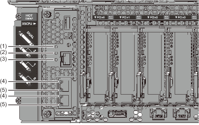
Figure 2-11 LED Locations on the XSCFU
|
|
| Location No. | Name | Color | State | Description |
|---|---|---|---|---|
| 1 | READY | Green | On | The XSCF is running. |
| Blinking | The XSCF is being started. | |||
| - | Off | The XSCF is stopped. (This includes the state where it has been disconnected from the building block configuration and is stopped.) |
||
| 2 | CHECK | Amber | On | A hardware error has occurred in the XSCFU. (It is normal if the LED goes on for several seconds and then goes off immediately after the power on.) |
| Blinking | Component that requires maintenance (This function is also called a locator.) |
|||
| - | Off | The XSCFU is in the normal state. Or no power is being supplied. | ||
| 3 | MASTER (SPARC M12-2S only) |
Green | On | The XSCF is operating as the master XSCF. |
| Blinking | The standby XSCF is switching over to the master XSCF. | |||
| - | Off | The XSCF is being started. Or the XSCF is operating as the standby or slave XSCF. |
| Location No. | Name | Color | State | Description |
| 4 | ACT | Green | Blinking | Indicates that data transmission/reception is ongoing. |
| - | Off | Indicates that data transmission/reception is not ongoing. | ||
| 5 | LINK SPEED | Amber | On | Indicates that the communication speed is 1 Gbps. |
| Green | On | Indicates that the communication speed is 100 Mbps. | ||
| - | Off | Indicates that the communication speed is 10 Mbps. |
CMU (on-board LAN port)
|
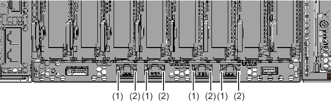
Figure 2-12 LED Locations on the CMU (On-Board LAN Ports)
|
|
| Location No. | Name | Color | State | Description |
| 1 | LINK SPEED | Green | On | Indicates that the communication speed is 10 Gbps. |
| Amber | On | Indicates that the communication speed is 1 Gbps. | ||
| - | Off | Indicates that the communication speed is 100 Mbps. | ||
| 2 | ACT | Green | Blinking | Indicates that data transmission/reception is ongoing. |
| - | Off | Indicates that data transmission/reception is not ongoing. |
FANU
|
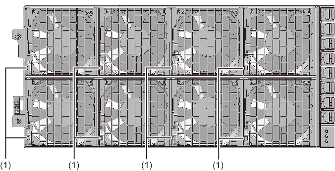
Figure 2-13 LED Locations on the FANU
|
|
| Location No. | Name | Color | State | Description |
|---|---|---|---|---|
| 1 | CHECK | Amber | On | Indicates that an error has occurred. |
| Blinking | Indicates that the unit (locator) requires maintenance. | |||
| - | Off | Indicates the normal state. |
PSU
|
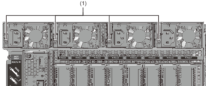
Figure 2-14 LED Locations on the PSU
|
|
| Location No. | Name | Color | State | Description |
| 1 | CHECK | Green | On | The input power is on, and power is being supplied normally. |
| Blinking | The power supply to this PSU is off. | |||
| Amber | On | A hardware error has occurred. The input power to this PSU is turned off in redundant operation. |
||
| Blinking | A hardware error has occurred, but this PSU is operating. | |||
| - | Off | Indicates that power is not being supplied. |
PCIe card slot
|
Figure 2-15 LED Locations of the PCIe Card Slots
|
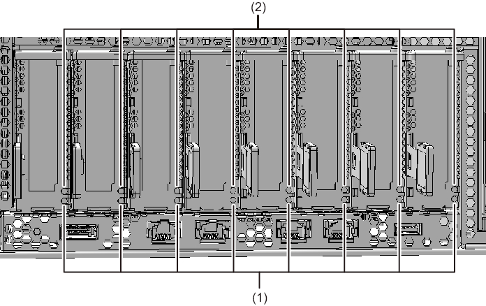
|
| Location No. | Name | Color | State | Description |
|---|---|---|---|---|
| 1 | POWER | Green | On | Indicates that power is being supplied. |
| - | Off | Indicates that power is not being supplied. | ||
| 2 | ATTENTION | Amber | On | Indicates that an error has occurred. |
| Blinking | Indicates that the unit (locator) requires maintenance. | |||
| - | Off | Indicates the normal state. |
HDD/SSD
|
Figure 2-16 LED Locations on the HDD/SSD
|
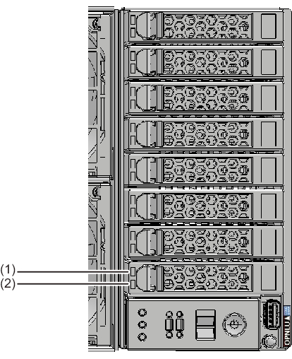
|
| Location No. | Name | Color | State | Description |
|---|---|---|---|---|
| 1 | READY | Green | Blinking | Indicates that the disk is being accessed. This LED is normally on, but it blinks while the disk is being accessed. While the LED is blinking, maintenance such as removal of the disk cannot be performed. |
| - | Off | Indicates that maintenance such as removal of the disk can be performed. | ||
| 2 | CHECK | Amber | On | Indicates that an error has occurred. |
| Blinking | Indicates that the unit (locator) requires maintenance. | |||
| - | Off | Indicates the normal state. |
< Previous Page | Next Page >