C.2 Understanding the Menu Configuration
C.2 Understanding the Menu Configuration
This section describes the menu configuration.
The configuration when the [Menu] bar is selected in the menu frame is shown below.
The configuration when the [Menu] bar is selected in the menu frame is shown below.
| Menu + XSCF + Status - System Overview - System Status - PPAR Status - PSB Status - Domain Status + PPAR Operation - PPAR Power - PPAR Mode Configuration - PPAR Configuration - PSB Configuration - Domain Configuration - PPAR Parameter - Verified Boot + Settings + Network - Current - Reserve + Service - Service State - HTTPS - SSH - Telnet - NTP - SMTP - SNMP - SNMP Security + User Manager - Account - LDAP - LDAP/SSL - Active Directory - Autologout - CoD Reservation - CoD Activation - Audit - Email Reporting - Time - Power Capping - Power Schedule - Add-In Card Manager - PCIBOX DIO - Remote Storage + Maintenance + Network Tools - Ping - Traceroute - Nslookup - Configuration Management - Firmware Update - Reboot XSCF - Switch Over - Snapshot - ASR + Logs - Error Log - Power Log - Event Log - Console Log - Panic Log - Environment Log - IPL Message Log - Monitor Message Log - Audit Log |
| Note - Each menu item is subject to change for functional improvement or other reasons. Also, the menu may differ depending on the model and conditions. |
Selecting a menu item displays the corresponding page in the main frame.
In the systems with multiple XSCFs, the [Switch Over] menu item is available, enabling XSCF switching. For an overview of the page targeted by each menu item, see "C.3 Available Pages."
In the systems with multiple XSCFs, the [Switch Over] menu item is available, enabling XSCF switching. For an overview of the page targeted by each menu item, see "C.3 Available Pages."
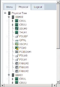
Figure C-2 shows a screen example where the [Physical] bar is selected in the menu frame.
|
Figure C-2 Physical Component Tree
|
|
| Note - The window layout and displayed content are just one example of the appearance and subject to change for functional improvement or other reasons. |
Selecting the [Physical] bar displays the components in this system in the form of a tree. The main frame displays the information/status of the component selected in the tree frame.
If the [Logical] bar is selected, the logical components belonging to the physical partition are displayed in the form of a tree. The main frame displays resource information regarding the CPU and memory belonging to the physical partition selected in the tree frame. For details on the resource information, see the showpparinfo(8) command man page or the Fujitsu SPARC M12 and Fujitsu M10/SPARC M10 XSCF Reference Manual. The main frame displays the information/status of the logical component, which belongs to the physical partition, selected in the tree frame.
If the [Logical] bar is selected, the logical components belonging to the physical partition are displayed in the form of a tree. The main frame displays resource information regarding the CPU and memory belonging to the physical partition selected in the tree frame. For details on the resource information, see the showpparinfo(8) command man page or the Fujitsu SPARC M12 and Fujitsu M10/SPARC M10 XSCF Reference Manual. The main frame displays the information/status of the logical component, which belongs to the physical partition, selected in the tree frame.
The component status display is as follows.
| Display | Overview |
|---|---|

|
Operating normally |

|
Not operating due to failure |

|
Any of the statuses below - Continuing operating although some components have failed or are degraded - Although component status is normal, degraded because other components have failed or are degraded - Component undergoing maintenance |
< Previous Page | Next Page >