8.14.5 Configuring Memory Mirroring to the CPU Chip
8.14.5 Configuring Memory Mirroring to the CPU Chip
Use the setupfru command of the XSCF firmware to configure memory mirroring.
For details on how to set memory mirror mode, see "14.1 Configuring Memory Mirroring." For details of the setupfru command, see the man page of the setupfru(8) command or the Fujitsu SPARC M12 and Fujitsu M10/SPARC M10 XSCF Reference Manual.
For details on how to set memory mirror mode, see "14.1 Configuring Memory Mirroring." For details of the setupfru command, see the man page of the setupfru(8) command or the Fujitsu SPARC M12 and Fujitsu M10/SPARC M10 XSCF Reference Manual.
Use the ldm list-socket command to show the list of the resources of each CPU socket.
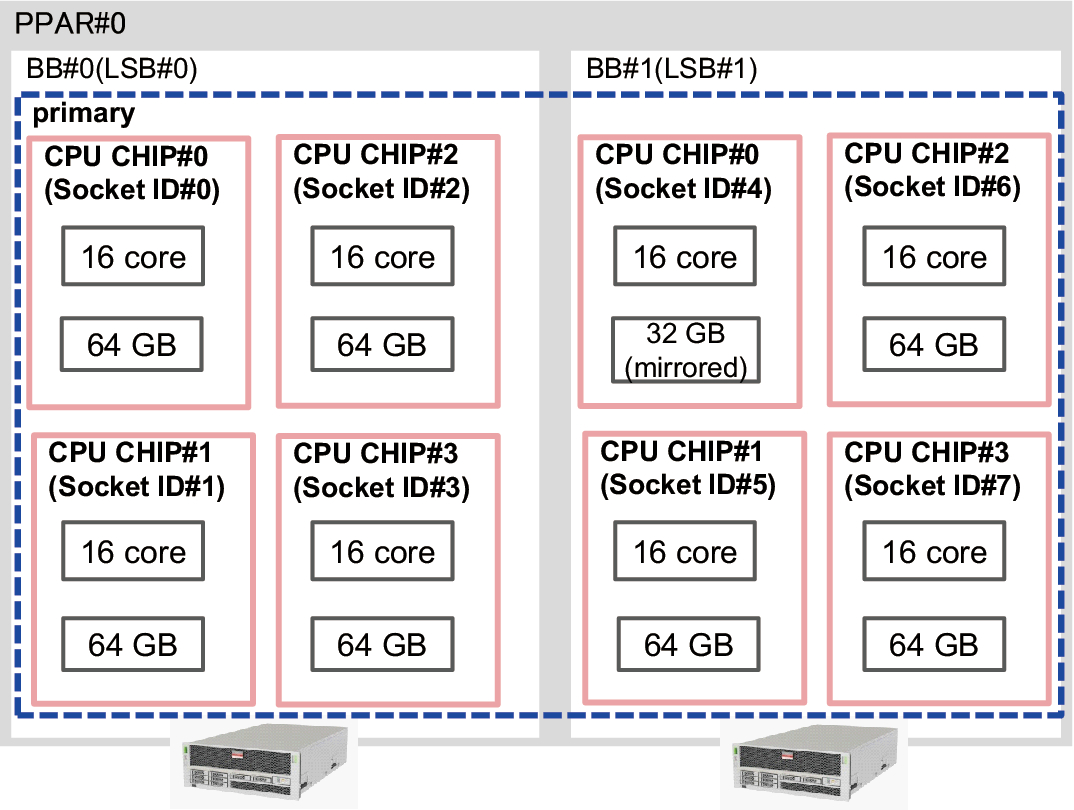
The following example shows that the size of the memory associated with CPU socket #4 decreases by half because memory mirror mode was set to CPU chip #0 in BB#1.
The following example shows that the size of the memory associated with CPU socket #4 decreases by half because memory mirror mode was set to CPU chip #0 in BB#1.
| # ldm list-socket CONSTRAINTS SOCKET TENANT VCPUS CORES SOCKET_ID GROUP primary 32 16 0 /BB0 primary 32 16 1 /BB0 primary 32 16 2 /BB0 primary 32 16 3 /BB0 primary 32 16 4 /BB1 primary 32 16 5 /BB1 primary 32 16 6 /BB1 primary 32 16 7 /BB1 MEMORY PA SIZE SOCKET_ID BOUND 0x700000000000 64G 7 primary 0x720000000000 64G 6 primary 0x740000000000 64G 5 primary 0x760050000000 31488M 4 primary 0x780000000000 64G 3 primary 0x7a0000000000 64G 2 primary 0x7c0000000000 64G 1 primary 0x7e0080000000 62G 0 primary IO NAME TYPE BUS SOCKET_ID BOUND PCIE0 BUS PCIE0 0 primary PCIE1 BUS PCIE1 0 primary PCIE2 BUS PCIE2 1 primary PCIE3 BUS PCIE3 1 primary PCIE4 BUS PCIE4 2 primary PCIE5 BUS PCIE5 2 primary PCIE6 BUS PCIE6 3 primary PCIE7 BUS PCIE7 3 primary PCIE8 BUS PCIE8 4 primary PCIE9 BUS PCIE9 4 primary PCIE10 BUS PCIE10 5 primary PCIE11 BUS PCIE11 5 primary PCIE12 BUS PCIE12 6 primary PCIE13 BUS PCIE13 6 primary PCIE14 BUS PCIE14 7 primary PCIE15 BUS PCIE15 7 primary |
Figure 8-3 shows a control domain in the physical partition that owns all the resources in the physical partition configured with two SPARC M10-4S units (BB#0 and BB#1).
|
Figure 8-3 CPU Cores and Memory in the Physical Partition
|
|
< Previous Page | Next Page >