3.9.3 XSCF Network Interface Configuration
3.9.3 XSCF Network Interface Configuration
This section describes the following XSCF network interfaces:
- The system control network that provides users with access to the XSCF (XSCF-LAN)
- Link network for communication between XSCFs (SSCP) (in a system with multiple XSCFs)
With a system consisting of only one SPARC M12/M10, two IP addresses are set for XSCF-LAN in order to access the XSCF. The XSCF-LAN can use only one LAN port.
With SPARC M12-2S systems consisting of 4 chassis or SPARC M10-4S systems consisting of 4 chassis that are directly connected, 4 IP addresses are set for XSCF-LAN, 2 IP addresses are set as takeover IP addresses, and 10 IP addresses are set for SSCP, for a total of 16 IP addresses.
With SPARC M12-2S systems consisting of 16 chassis or SPARC M10-4S systems consisting of 16 chassis that are connected by 4 crossbar boxes, 4 IP addresses are set for XSCF-LAN, 2 IP addresses are set as takeover IP addresses, and 44 IP addresses are set for SSCP, for a total of 50 IP addresses.
| Note - If the system has multiple XSCFs, the XSCFs cannot be configured from the standby XSCF. Commands for configuring all the XSCFs are executed only from the master XSCF. |
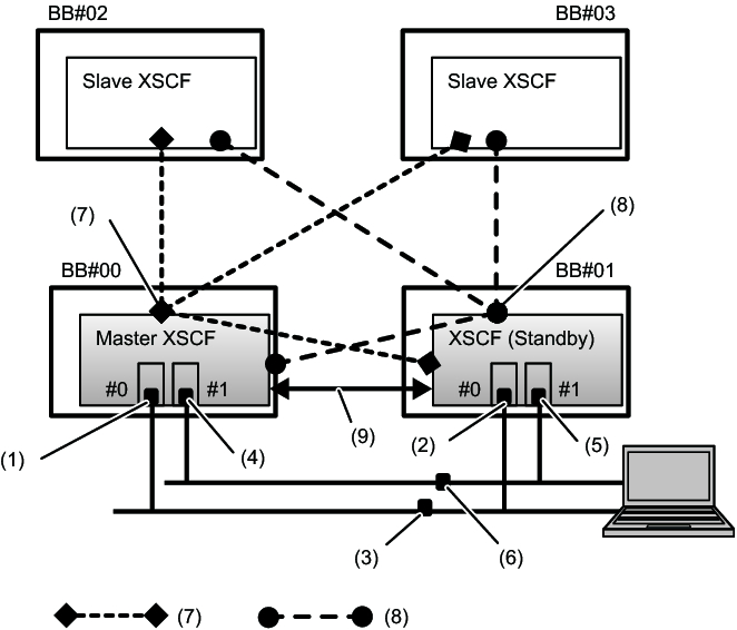
Figure 3-4 shows the necessary network interfaces for configuring the XSCF network for the SPARC M12-2S or SPARC M10-4S system in the 4BB configuration, with chassis directly interconnected.
|
Figure 3-4 XSCF Network in the 4BB Configuration
|
|
| No. |
Address Setting | No. |
Address Setting |
|---|---|---|---|
| 1 | XSCF-LAN#0 address (on master XSCF side) | 6 | Inter-XSCF-LAN#1 takeover IP address |
| 2 | XSCF-LAN#0 address (on standby XSCF side) | 7 | SSCP address (master XSCF and XSCF in each BB#xx): 4 addresses |
| 3 | Inter-XSCF-LAN#0 takeover IP address | 8 | SSCP address (standby XSCF and XSCF in each BB#xx): 4 addresses |
| 4 | XSCF-LAN#1 address (on master XSCF side) | 9 | SSCP address for duplication (master XSCF and standby XSCF): 2 addresses |
| 5 | XSCF-LAN#1 address (on standby XSCF side) |
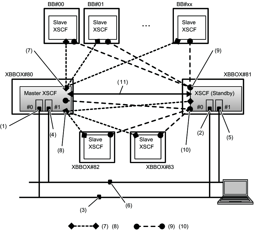
Figure 3-5 shows an example of the necessary network interfaces for configuring the XSCF network for the SPARC M12-2S or SPARC M10-4S system with crossbar boxes.
|
Figure 3-5 XSCF Network in a System Configuration with Crossbar Boxes
|
|
| No. |
Address Setting | No. |
Address Setting |
|---|---|---|---|
| 1 | XSCF-LAN#0 address (on master XSCF side) | 7 | SSCP address (master XSCF and XSCF in each BB#xx): 17 addresses |
| 2 | XSCF-LAN#0 address (on standby XSCF side) | 8 | SSCP address (master XSCF and XSCFs in each XBBOX#xx): 4 addresses |
| 3 | Inter-XSCF-LAN#0 takeover IP address | 9 | SSCP address (standby XSCF and XSCF in each BB#xx): 17 addresses |
| 4 | XSCF-LAN#1 address (on master XSCF side) | 10 | SSCP address (standby XSCF and XSCF in each XBBOX#xx): 4 addresses |
| 5 | XSCF-LAN#1 address (on standby XSCF side) | 11 | SSCP address for duplication (master XSCF and standby XSCF): 2 addresses |
| 6 | Inter-XSCF-LAN#1 takeover IP address |
< Previous Page | Next Page >