3.9.2 Understanding the XSCF Network Interfaces
3.9.2 Understanding the XSCF Network Interfaces
XSCF Ethernet Port
Each SPARC M12/M10 chassis and crossbar box has two XSCF Ethernet ports. The ports are named XSCF-LAN#0 and XSCF-LAN#1.
Both use an RJ-45 connector, supporting 10Base-T/100Base-TX/1000Base-T. The XSCF-LAN ports are ports for the LAN connection used by the system administrator to perform operations using the XSCF shell or XSCF Web. The operations include displaying the server status, operating a domain, and displaying a console.
To connect to the XSCF network, specify the IP addresses of these Ethernet ports. Users can maintain/manage the server using the two LAN paths.
For a system that has multiple XSCFs, the XSCF-LAN ports of the slave XSCFs are not used for the purpose of server maintenance/management. The XSCF-LAN ports of the slave XSCFs are connected to the network only when remote storage is used. For details on remote storage, see "4.6 Using Remote Storage."
Takeover IP Address Between the Master XSCF and Standby XSCF
If the system has multiple XSCFs, XSCF-LAN#0 and XSCF-LAN#1 on the master XSCF and standby XSCF are respectively grouped together so that one takeover IP address (virtual IP address) can be set for the groups. As a result, even if the chassis housing the master XSCF and standby XSCF are switched, users need not be concerned about the IP addresses of the master XSCF and standby XSCF. By continuing to use the takeover IP address, they can access the master XSCF even after the switchover.
Protocol for SP to SP Communication (SSCP)
If the system has multiple XSCFs, a network is configured between the XSCFs. The protocol for the network interface between these XSCFs is referred to as the protocol for SP to SP communication (SSCP) or the SSCP link network. Through its communication paths, the XSCFs are connected to one another, mutually monitor one another's status, and exchange system information.
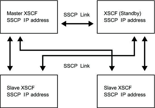
Figure 3-3 shows an SSCP link network using a SPARC M12-2S or SPARC M10-4S system in the 4BB configuration, with chassis directly interconnected.
Figure 3-3 shows an SSCP link network using a SPARC M12-2S or SPARC M10-4S system in the 4BB configuration, with chassis directly interconnected.
|
Figure 3-3 SSCP Link Network
|
|
For configuring SSCP, the respective cables connect the master XSCF to the standby XSCF, the master XSCF to the slave XSCFs, and the standby XSCF to the slave XSCFs. For the connection between the master XSCF and the standby XSCF, the XSCF DUAL control ports are connected to each other. The SSCP port for connecting the master or standby to each slave is called the XSCF BB control port. The slave XSCFs are not mutually connected. For details on cable connections to configure SSCP, see "Chapter 4 Setting the SPARC M12-2S in a Building Block Configuration" in the Fujitsu SPARC M12-2S Installation Guide or "Chapter 4 Configuring Building Block Connections" in the Fujitsu M10-4S/SPARC M10-4S Installation Guide.
The SSCP IP address was set at factory shipment beforehand. If you want to set a different SSCP IP address, the setting needs to be made at the same time that the initial settings for the system are made. For details on the SSCP IP addresses, see "3.9.5 Understanding the IP Addresses that are Set with SSCP."
The SSCP IP address was set at factory shipment beforehand. If you want to set a different SSCP IP address, the setting needs to be made at the same time that the initial settings for the system are made. For details on the SSCP IP addresses, see "3.9.5 Understanding the IP Addresses that are Set with SSCP."
< Previous Page | Next Page >