1.1 Basics of the SPARC M12/M10
1.1 Basics of the SPARC M12/M10
This section provides an overview of the SPARC M12/M10 systems.
The SPARC M12/M10 is a UNIX server system that uses the SPARC processor and Oracle Solaris. CPU Activation allows the expansion of resources in units of one core in phases. The SPARC M12-2S/M10-4S uses a building block system so that the system can be configured as appropriate for the intended business use and the scale of business. The servers can be applied in many ways; as the database servers best-suited for data centers in an era of cloud computing, and as the Web servers or application servers for which high throughput is demanded.
The following models have been prepared to support various intended uses.
- SPARC M12-1
This 1-CPU compact model with six cores at maximum is designed for space saving and high performance. - SPARC M12-2
This model consists of up to two CPUs, each of which has up to 12 cores. - SPARC M12-2S
This model consists of up to two CPUs, each of which has up to 12 cores. With the building block (BB) system, the number of connected SPARC M12-2S units can be adjusted according to the performance required. A configuration can be expanded to up to four BBs by connecting the SPARC M12-2S units directly to one another. Moreover, a system that uses crossbar boxes supports a configuration of up to 16 BBs and scales up to 32 CPUs--the scalability is ensured. - SPARC M10-1
This 1-CPU compact model with 16 cores at maximum is designed for space saving and high performance. - SPARC M10-4
This model consists of up to four CPUs, each of which has up to 16 cores. - SPARC M10-4S
This model consists of up to four CPUs, each of which has up to 16 cores. With the building block (BB) system, the number of connected SPARC M10-4S units can be adjusted according to the performance required. A configuration can be expanded to up to four BBs by connecting the SPARC M10-4S units directly to one another. Moreover, a system that uses crossbar boxes supports a configuration of up to 16 BBs and scales up to 64 CPUs--the scalability is ensured.
| Note - If the building block system is used, the SPARC M12-2S and SPARC M10-4S cannot be mixed in the same configuration. |
System configuration
This section describes the system configuration.
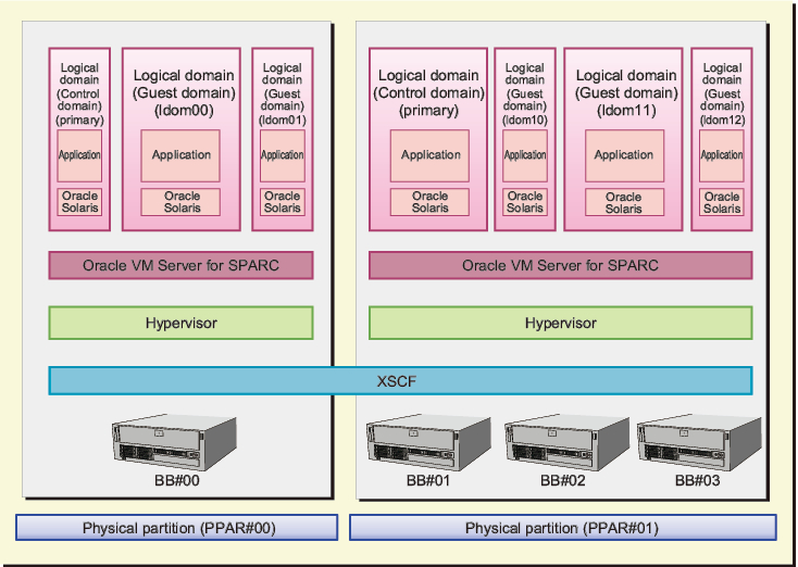
Figure 1-1 shows an example of a system configuration where more than one SPARC M12-2S or more than one SPARC M10-4S is connected by the building block system. A single SPARC M12-2S/M10-4S unit that can have a building block configuration is one building block. A physical partition (PPAR) is configured by combining one or more building blocks.
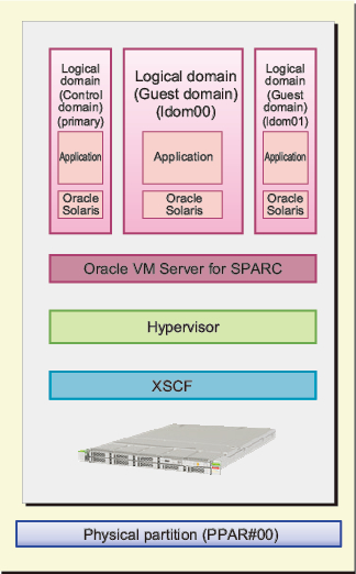
Figure 1-2 shows an example of a system configuration of SPARC M12-1/M12-2/M10-1/M10-4. A single SPARC M12-1/M12-2/M10-1/M10-4 unit cannot have a building block configuration yet it is sometimes called a physical partition. Note that the SPARC M12-2S and SPARC M10-4S in a single unit configuration is also sometimes called a physical partition.
Figure 1-1 shows an example of a system configuration where more than one SPARC M12-2S or more than one SPARC M10-4S is connected by the building block system. A single SPARC M12-2S/M10-4S unit that can have a building block configuration is one building block. A physical partition (PPAR) is configured by combining one or more building blocks.
Figure 1-2 shows an example of a system configuration of SPARC M12-1/M12-2/M10-1/M10-4. A single SPARC M12-1/M12-2/M10-1/M10-4 unit cannot have a building block configuration yet it is sometimes called a physical partition. Note that the SPARC M12-2S and SPARC M10-4S in a single unit configuration is also sometimes called a physical partition.
|
Figure 1-1 Example of a SPARC M12-2S/M10-4S System Configuration
|
|
|
Figure 1-2 Example of a SPARC M12-1/M12-2/M10-1/M10-4 System Configuration
|
|
The following sections describe "physical partitions" and "logical domains," which are key to the system configuration.
Configuration of Physical Partitions
To configure a SPARC M12-2S or SPARC M10-4S system, configure a physical partition (PPAR) by combining one or more building blocks of the same model. Configuring physical partitions is called partitioning, and the resulting configured object is called a physical partition (PPAR). Physical partitions are configured using the XSCF firmware, which is the system management firmware.
In the example shown in Figure 1-1, PPAR#00 is one of the building blocks (BBs), and BB#00 is configured as the physical partition PPAR#00. Similarly, physical partition PPAR#01 is configured from BB#01, BB#02, and BB#03.
Once a physical partition is configured, hardware resources on the physical partition are assigned to logical domains.
Note that since the SPARC M12-1/M12-2/M10-1/M10-4 is a model consisting of a single unit, it can be configured with only one physical partition.
Configuration of Logical Domains
A physical partition has the CPUs, memory, I/O devices, and other hardware resources to be assigned to logical domains. A logical domain is configured using the Oracle VM Server for SPARC software.
A configured logical domain is handled as one UNIX system on the software side. Oracle Solaris and applications can be installed in logical domains and applied to tasks separately. In the example shown in Figure 1-1, the logical domains primary, ldom00, and ldom01 are configured with the assignment of hardware resources of the physical partition PPAR#00.
Similarly, the logical domains primary, ldom10, ldom11, and ldom12 are configured with the physical partition PPAR#01.
One of the logical domains, to which physical partition resources are assigned, serves as the domain controlling all the logical domains. It is called the control domain. The control domain, which is the logical domain controller, also serves to handle communication between the physical partition and logical domains.
Firmware/Software Required for the Systems
The physical partitions are implemented with the XSCF firmware and the logical domain, Oracle VM Server for SPARC. Even for a configuration of only the control domain, Oracle VM Server for SPARC is required.
Between the XSCF firmware and Oracle VM Server for SPARC, communication for monitoring and managing the whole system is handled inside the system. Users do not need to pay attention to that.
Between the XSCF firmware and Oracle VM Server for SPARC, communication for monitoring and managing the whole system is handled inside the system. Users do not need to pay attention to that.
The interface between the XSCF firmware and Oracle VM Server for SPARC in the SPARC M12/M10 systems is implemented by firmware named Hypervisor.
"1.2 Basics of the XSCF Firmware" and subsequent sections describe firmware and software used in the systems.
< Previous Page | Next Page >