1.2.5 Differences in XSCF Configurations by Model
1.2.5 Differences in XSCF Configurations by Model
This section describes how XSCFs are configured and how the system is monitored and managed in the respective configurations of the SPARC M12/M10.
SPARC M12-1/M12-2/M10-1/M10-4, and SPARC M12-2S/M10-4S in a Single-Unit Configuration
The SPARC M12-1/M12-2/M10-1/M10-4 and the SPARC M12-2S/M10-4S in a single-unit configuration each have a configuration with only one XSCF. There is no standby XSCF or slave XSCF.
SPARC M12-2S/M10-4S in a Building Block Configuration (No Crossbar Box)
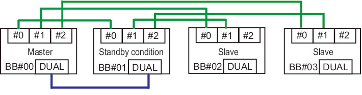
The SPARC M12-2S/M10-4S system in a building block configuration with no crossbar box is configured with up to four SPARC M12-2S or SPARC M10-4S chassis, so the configuration has up to four XSCFs accordingly. In this case, the XSCF in the BB#00 or BB#01 chassis is the master XSCF or standby XSCF. If a failure occurs in the master XSCF, the standby XSCF switches to the master XSCF. The BB#02 and BB#03 chassis are fixed as slave XSCFs.
- Forms of connection
The XSCF BB control port of the master XSCF (BB#00 in Figure 1-7) is connected to the XSCF BB control port with network ID 0 (#0 port of BB#01 to BB#03 in Figure 1-7) on each slave XSCF.
The XSCF BB control port of the standby XSCF (BB#01 in Figure 1-7) is connected to the XSCF BB control port with network ID 1 (#1 port of BB#02 and BB#03 in Figure 1-7) on each slave XSCF. The master XSCF and standby XSCF are connected by the XSCF DUAL control ports. The slave XSCFs are connected only to the master XSCF and standby XSCF.
- XSCF control flow
The master XSCF monitors and manages all the XSCFs. In principle, the various settings for XSCFs are made from the master XSCF. The settings made with the master XSCF are reflected on all slave XSCFs, including the standby XSCF, through the SSCP network. Also, the settings made with the master XSCF for a given SPARC M12-2S or SPARC M10-4S chassis are also reflected on the standby XSCF and the slave XSCFs in the intended SPARC M12-2S or SPARC M10-4S chassis.
|
Figure 1-7 XSCF Connections (for the SPARC M12-2S/M10-4S in a Building Block Configuration (No Crossbar Box))
|
|
SPARC M12-2S/M10-4S in a Building Block Configuration (With Crossbar Boxes)
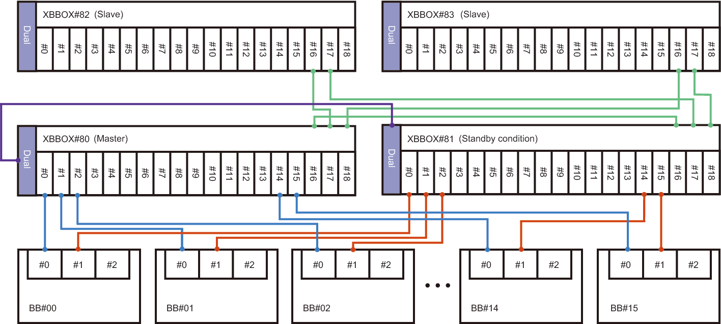
The SPARC M12-2S or SPARC M10-4S in a building block configuration (with crossbar boxes) is configured with up to 16 XSCFs, or the crossbar boxes with up to four XSCFs. In this case, the XSCF in the XBBOX#80 or XBBOX#81 crossbar box is the master XSCF or standby XSCF. The XSCFs in the XBBOX#82 and XBBOX#83 crossbar boxes and in all SPARC M12-2S or SPARC M10-4S chassis are fixed as slave XSCFs.
- Forms of connection
- Connections to crossbar boxes
The master XSCF (XBBOX#80) is connected to the XSCF BB control port with network ID 16 (#16 port of XBBOX#81 to XBBOX#83 in Figure 1-8) on each slave XSCF. The standby XSCF (XBBOX#81) is connected to the XSCF BB control port with network ID 17 (#17 port of XBBOX#82 and XBBOX#83 in Figure 1-8) on each slave XSCF. The master XSCF and standby XSCF are connected by the XSCF DUAL control ports. Connection is not made to any XSCF other than the master XSCF and standby XSCF.
- Connections to the SPARC M12-2S/M10-4S
The master XSCF (XBBOX#80) is connected to the XSCF BB control port with network ID 0 (#0 port of BB#00 to BB#15 in Figure 1-8) on each slave XSCF. The standby XSCF (XBBOX#81) is connected to the XSCF BB control port with network ID 1 (#1 port of BB#00 to BB#15 in Figure 1-8) on each slave XSCF. The XSCFs fixed as slave XSCFs (BB#00 to BB#15) are connected only to the master XSCF and standby XSCF.
- XSCF control flow
- The master XSCF monitors and manages all the XSCFs. In principle, the various settings for XSCFs are made from the master XSCF. The settings made with the master XSCF are reflected on all slave XSCFs, including the standby XSCF, through the SSCP network. Also, the settings made with the master XSCF for a given SPARC M12-2S or SPARC M10-4S chassis are also reflected on the standby XSCF and the slave XSCFs in the intended SPARC M12-2S or SPARC M10-4S chassis.
|
Figure 1-8 XSCF Connections (for the SPARC M12-2S/M10-4S in a Building Block Configuration (With Crossbar Boxes))
|
|
< Previous Page | Next Page >