6.1.3 Using the POWER Switch
6.1.3 Using the POWER Switch
Press the POWER switch on the operation panel on the chassis that has the master XSCF. Pressing the POWER switch starts the supply of power in the proper order to all the physical partitions in the system. After that, all the logical domains in each physical partition are started in the proper order.
| Note - Only the POWER switch on the chassis that has the master XSCF is functional. The POWER switches on the other chassis cannot power on the system. |
| Note - If the setpparparam command of the XSCF firmware has suppressed auto boot of a control domain, the suppressed control domain is not started. Furthermore, if the setpparmode command has suppressed auto boot of a physical partition and logical domains, the suppressed logical domains are not started. For details of the setpparparam and setpparmode commands, see the setpparparam(8) and setpparmode(8) command man pages or the Fujitsu SPARC M12 and Fujitsu M10/SPARC M10 XSCF Reference Manual. |
The chassis that has the master XSCF varies depending on the model.
- SPARC M12-1
POWER switch on the SPARC M12-1 - SPARC M12-2
POWER switch on the SPARC M12-2 - SPARC M12-2S (no crossbar box)
POWER switch on BB#00 or BB#01 (chassis whose MASTER LED is on) of the SPARC M12-2S - SPARC M12-2S (with crossbar boxes)
POWER switch on the crossbar box XBBOX#80 or XBBOX#81 (chassis whose MASTER LED is on) - SPARC M10-1
POWER switch on the SPARC M10-1 - SPARC M10-4
POWER switch on the SPARC M10-4 - SPARC M10-4S (no crossbar box)
POWER switch on BB#00 or BB#01 (chassis whose MASTER LED is on) of the SPARC M10-4S - SPARC M10-4S (with crossbar boxes)
POWER switch on the crossbar box XBBOX#80 or XBBOX#81 (chassis whose MASTER LED is on)
For details on the switches and LEDs on the operation panel, see the Service Manual for your server.
|
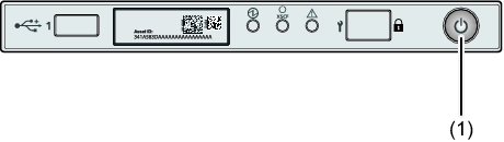
Figure 6-2 Operation Panel (SPARC M12-1/M10-1)
|
|
| No. | Component |
|---|---|
| 1 | POWER switch |
|
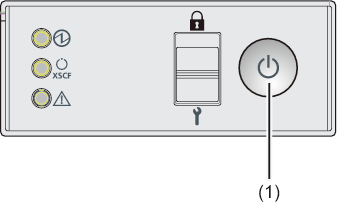
Figure 6-3 Operation Panel (SPARC M12-2/M10-4)
|
|
| No. | Component |
|---|---|
| 1 | POWER switch |
|
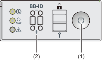
Figure 6-4 Operation Panel (SPARC M12-2S/M10-4S Crossbar Box)
|
 "/> "/>
|
| No. | Component |
|---|---|
| 1 | POWER switch |
| 2 | BB-ID switch |
Operation Procedure
- Press the POWER switch on the operation panel of the chassis that has the master XSCF.
All the physical partitions in the system are started. After that, all the logical domains in each physical partition are started.
< Previous Page | Next Page >