1.3.1 Overview of Network Connections
1.3.1 Overview of Network Connections
This section provides an overview of the network connections for system operation.
The system consists of two major networks. One is the user network, and the other is the system control network.
The system consists of two major networks. One is the user network, and the other is the system control network.
- User network
The user network is used to run the configured system in business. The user network is connected to other servers, other PCs, and peripherals as required for tasks, and configured accordingly.
The user network environment is kept secure with the installation of a firewall and other security measures as needed when the network can be connected externally to the Internet. - System control network (XSCF network)
The system control network (XSCF network) is used for system maintenance and management. Other uses of this network include operations of the XSCF firmware, which is used to monitor and manage the system, power-on/off operations, and component replacement operations. To perform operations for remote system control, the system control network is set up in an environment configured for the operations.
Though the system control network can be connected to the user network too, security measures such as a firewall must be installed for higher security to prevent unauthorized external access to the system control network.
The terminal used for system maintenance and management (system management terminal) is connected via a serial or LAN connection, according to the situation. For the forms of connection of the system management terminal, see "2.1 Connecting the System Management Terminal."
The following example shows a SPARC M12/M10 system configuration.
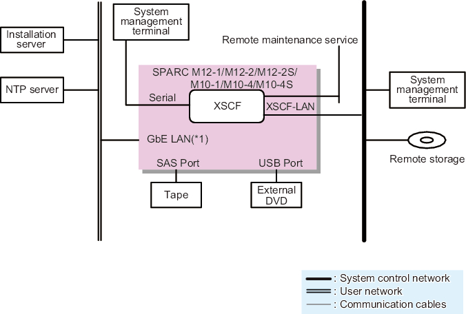
Figure 1-9 shows a configuration that uses one SPARC M12/M10.
The system management terminal is connected to the XSCF-LAN port via the serial port or the system control network. The remote storage is connected to the XSCF-LAN port via the system control network. The installation server and others are connected to the on-board GbE and 10GbE LAN ports or each PCIe slot LAN port via the user network. Moreover, the external SAS interface devices such as a tape unit are connected to the SAS ports, and the external USB interface devices such as an external DVD drive are connected to the USB ports.
|
Figure 1-9 Configuration Example of Connections of the Single-Unit Configuration of the SPARC M12-1/M12-2/M12-2S/M10-1/M10-4/M10-4S
|
|
*1 Example of the on-board LAN of the SPARC M10
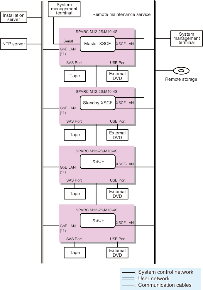
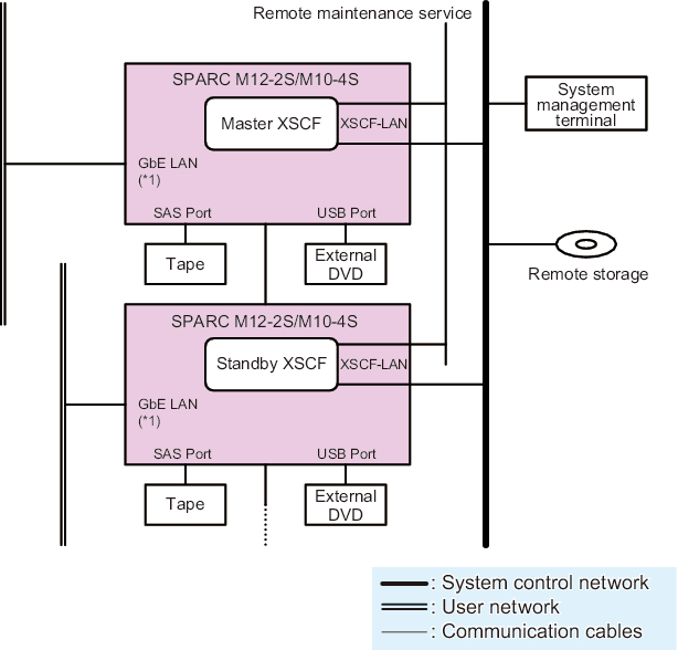
Figure 1-10 shows a configuration that has four SPARC M12-2S or SPARC M10-4S units connected without using crossbar boxes.
The system management terminal is connected to the serial port of the master XSCF or to the XSCF-LAN ports of the master XSCF and standby XSCF via the system control network. The remote storage is connected to the XSCF-LAN port via the system control network. The installation server and others are connected to the on-board GbE and 10GbE LAN ports or each PCIe slot LAN port via the user network. Moreover, the external SAS interface devices such as a tape unit are connected to the SAS ports, and the external USB interface devices such as an external DVD drive are connected to the USB ports.
The system management terminal is connected to the serial port of the master XSCF or to the XSCF-LAN ports of the master XSCF and standby XSCF via the system control network. The remote storage is connected to the XSCF-LAN port via the system control network. The installation server and others are connected to the on-board GbE and 10GbE LAN ports or each PCIe slot LAN port via the user network. Moreover, the external SAS interface devices such as a tape unit are connected to the SAS ports, and the external USB interface devices such as an external DVD drive are connected to the USB ports.
|
Figure 1-10 Configuration Example of SPARC M12-2S/M10-4S Connections (No Crossbar Box)
|
|
*1 Example of the on-board LAN of the SPARC M10
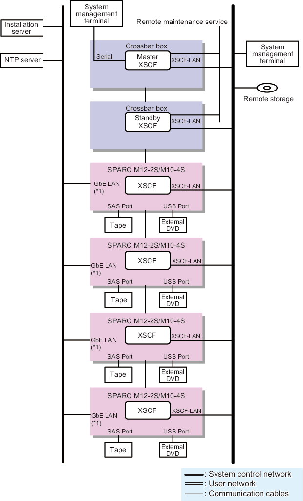
Figure 1-11 shows a configuration that has multiple SPARC M12-2S or SPARC M10-4S units connected through crossbar boxes.
The system management terminal is connected to the serial port of the master XSCF in the crossbar box or to the XSCF-LAN ports of the master XSCF and standby XSCF via the system control network. The remote storage is connected to the XSCF-LAN of each SPARC M12-2S or SPARC M10-4S unit via the system control network.
The installation server and others are connected to the on-board GbE and 10GbE LAN ports or each PCIe slot LAN port via the user network. Moreover, the external SAS interface devices such as a tape unit are connected to the SAS ports of the SPARC M12-2S or SPARC M10-4S units, and the external USB interface devices such as an external DVD drive are connected to the USB ports.
|
Figure 1-11 Configuration of SPARC M12-2S/M10-4S Connections (With Crossbar Boxes)
|
|
*1 Example of the on-board LAN of the SPARC M10
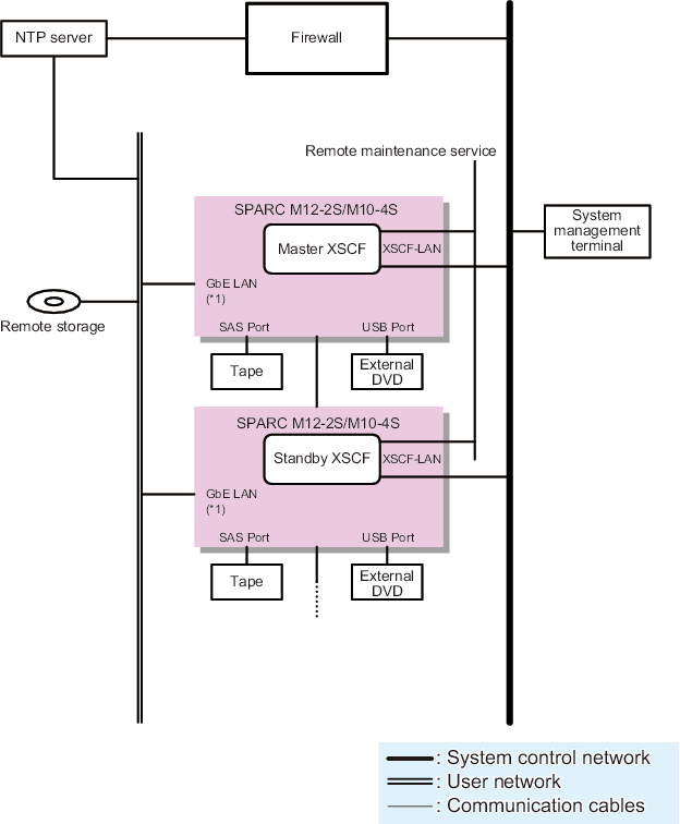
Figure 1-12 shows a configuration that connects the system control network and user network through the firewall.
Here, to use an NTP server to synchronize the time of the XSCFs, the NTP server on the user network is connected through the firewall. The connection through the firewall can protect the XSCFs from security threats on the user network.
For the remote storage placed on the user network, you can connect it to the XSCF-LAN while protecting it from security threats by configuring remote storage access in the firewall.
|
Figure 1-12 Configuration Connecting the System Control Network and User Network
|
|
*1 Example of the on-board LAN of the SPARC M10
Figure 1-13 shows a system in a building block configuration where each SPARC M12-2S or SPARC M10-4S unit is connected to a separate user network.
Separating the user network segment connected to the on-board GbE/10GbE LAN or each PCIe slot LAN of each SPARC M12-2S or SPARC M10-4S unit reduces the risk from security threats on the user networks.
The system control network cannot be separated for each SPARC M12-2S or SPARC M10-4S unit in a building block configuration.
|
Figure 1-13 Configuration Separating the User Network Segment of Each Server
|
|
*1 Example of the on-board LAN of the SPARC M10
< Previous Page | Next Page >