1.2.2 XSCF Features
1.2.2 XSCF Features
Built-in user interface used for daily server operation and maintenance
You can get a grasp of the server status, operate the server, and service the server by accessing the XSCF from the command line or a Web browser.
- XSCF shell (command-line interface)
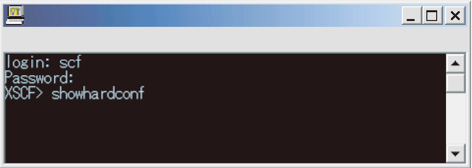
You can connect a user PC to the server directly through a serial cable, or connect an Ethernet connection with the XSCF LAN, and perform communications using the SSH service or Telnet service. As a result, the PC can be used as an XSCF shell terminal, which can execute XSCF shell commands. On the XSCF shell, you can switch to a console from which you can operate the control domain (referred to below as the control domain console).
- Figure 1-3 shows an example of the XSCF shell terminal.
|
Figure 1-3 Example of the XSCF shell terminal
|
|
- XSCF Web (browser user interface)
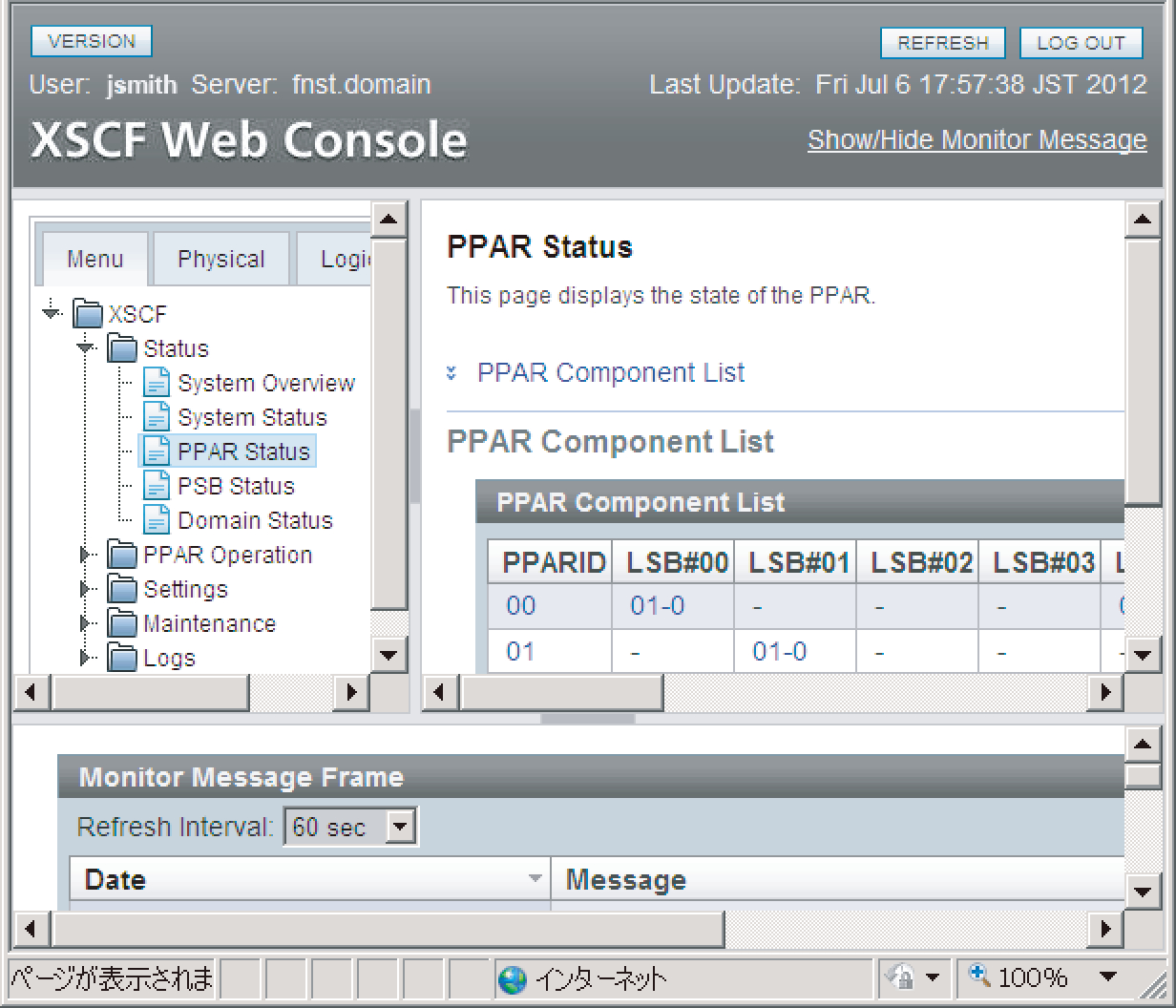
This interface allows you to connect a user PC to the XSCF LAN via Ethernet and perform communications using the HTTPS and SSL/TLS protocols. As a result, you can use a Web browser on the PC for using the XSCF Web console. With XSCF Web, you can lessen the load of operations by users and reduce server management costs by displaying components in a hierarchical view and finding the operations for those purposes from a menu.
Figure 1-4 shows an example of using the XSCF Web console.
|
Figure 1-4 Example of the XSCF Web Console
|
|
XSCF in the building block configuration
When the system is configured using the building block system, the crossbar box (XBBOX) also contains XSCF. Mounting the XSCF in the server and XBBOX implements a highly reliable system.
| Note - If a system is configured using the building block system, SPARC M12-2S and SPARC M10-4S chassis cannot be mixed in the configuration. |
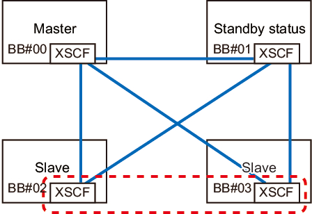
Figure 1-5 shows an example of a SPARC M12-2S or SPARC M10-4S system in the 4BB configuration, with chassis directly interconnected.
|
Figure 1-5 Example of a SPARC M12-2S/M10-4S System XSCF Configuration (No Crossbar Box)
|
|
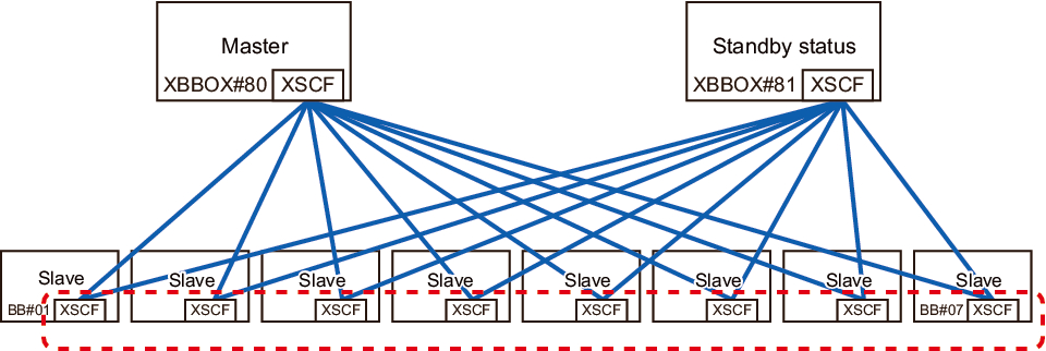
Figure 1-6 shows an example of a SPARC M12-2S or SPARC M10-4S in the 8BB configuration with a crossbar box.
|
Figure 1-6 Example of a SPARC M12-2S/M10-4S System XSCF Configuration (With Crossbar Boxes)
|
|
XSCFs in the building block configuration are classified into three roles: master, standby, and slave. For details, see "1.2.4 Master/Standby/Slave XSCF Mechanism."
External Interfaces
The individual chassis and crossbar boxes in the SPARC M12/M10 have the following XSCF-related connectors (ports) and LEDs mounted. Users, system administrators, and field engineers can monitor and operate the servers by using these interfaces and the XSCF firmware.
For the location of each interface and details on the connection method, see either of the following.
For the location of each interface and details on the connection method, see either of the following.
- "Checking External Interface Port Specifications" in the Installation Guide for your server
- "Understanding the LED Indications" in the Service Manual for your server
- Serial port
The serial port is used with the XSCF shell to configure the server and display the server status. The serial port (RS-232C) uses an RJ-45 connector. The connection between the serial port and a PC uses an RS-232C serial cross cable. If you connect with a LAN cable, the connection needs an RJ-45/RS-232C conversion cable or conversion connector. - XSCF-LAN port (Ethernet port)
The XSCF-LAN port is the port for the LAN connection used by the system administrator to operate the server via Ethernet. Through the XSCF-LAN port, the system administrator configures the server and displays the server status by using the XSCF shell or XSCF Web. There are two XSCF-LAN ports. Both ports use an RJ-45 connector. Each port supports only 10Base-T/100Base-TX/1000Base-T auto negotiation. The connection speed/connection mode of the XSCF-LAN cannot be set. - USB ports
The front panel has one USB port (Type-A) and the rear panel has two USB ports for connections with USB devices. Use these USB ports to, for example, connect a DVD drive to install Oracle Solaris. The XSCF-dedicated USB port on the rear panel supports the USB 1.1 or USB2.0 interface. Use it to save and restore XSCF hardware information and to collect log information. - LEDs
The following LEDs relate to the XSCF and XSCF-LAN.- READY LED (green)
The READY LED goes on in green. The READY LED starts blinking immediately after the input power is turned on. The blinking indicates that the XSCF is starting and being initialized. Once the XSCF initialization ends, the LED stops blinking and stays on.- CHECK LED (amber)
The CHECK LED goes on in amber. The CHECK LED goes on immediately after the input power is turned on. However, the CHECK LED stays off while the hardware operates normally. It goes on when the hardware has some kind of failure.- MASTER LED (green, only for the SPARC M12-2S/M10-4S system)
The MASTER LED goes on in green. The MASTER LED indicates the SPARC M12-2S chassis, SPARC M10-4S chassis, or crossbar box that has the master XSCF, in a system with multiple XSCFs. It goes on for the master XSCF and stays off for the standby and slave XSCFs.- LINK SPEED (green or amber)
Each XSCF-LAN port has the Link Speed LED, which goes on in green or amber. The Link Speed LED goes on in amber with a 1000-Mbps LAN connection and goes on in green with a 100-Mbps LAN connection. It goes out with a 10-Mbps LAN connection.- ACT LED (green)
Each XSCF-LAN port has the ACT LED, which goes on in green. It blinks in green while data is being sent or received. It goes out while data is not being sent or received. - Protocol for SP to SP communication port (SSCP port)
In the system with a building block configuration and multiple XSCFs, the following connectors (ports) are mounted on each SPARC M12-2S or SPARC M10-4S chassis and crossbar boxes because communications are made between service processors. For the configuration of connections between XSCFs, see "Chapter 4 Setting the SPARC M12-2S in a Building Block Configuration" in the Fujitsu SPARC M12-2S Installation Guide or "Chapter 4 Configuring Building Block Connections" in the Fujitsu M10-4S/SPARC M10-4S Installation Guide.- SPARC M12-2S/M10-4S side
XSCF DUAL control port: 1 port. This port connects the master and standby XSCFs together.
XSCF BB control port: 3 ports. These ports connect the master and standby XSCFs to slave XSCFs.- Crossbar box side
XSCF DUAL control port: 1 port. This port connects the master and standby XSCFs together.
XSCF BB control port: 19 ports. These ports connect the master and standby XSCFs to slave XSCFs.
< Previous Page | Next Page >