4.6.2 Remote Storage Network Configuration
4.6.2 Remote Storage Network Configuration
Network Configuration
Remote storage uses the XSCF-LAN network of the SPARC M12/M10 to implement access to media in terminals.
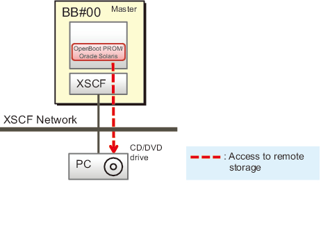
Figure 4-7 shows the network configuration when using remote storage, where the system is configured with only one SPARC M12/M10.
Figure 4-7 shows the network configuration when using remote storage, where the system is configured with only one SPARC M12/M10.
|
Figure 4-7 System Configured With Only One SPARC M12/M10
|
|
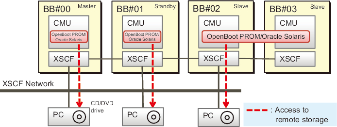
Figure 4-8 shows the network configuration when using remote storage in the system in a building block configuration (with no crossbar boxes). The LAN of the master XSCF and system management terminal, the XSCF-LAN used with remote storage, and the LAN of terminals are connected in the same subnet.
|
Figure 4-8 Remote Storage Network Configuration (No Crossbar Box)
|
|
| Note - If there is only one PC, you can even use the remote storage from each SPARC M12/M10 by switching the connecting SPARC M12/M10 system chassis each time. |
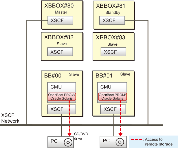
Figure 4-9 shows the network configuration when using remote storage, where the system in a building block configuration is connected to a crossbar box. When using remote storage, do not use the XSCF-LAN of the crossbar box chassis to connect to media. Use the XSCF-LAN of the SPARC M12/M10, which is a slave chassis.
In Figure 4-9, the LAN of the master XSCF and system management terminal, the XSCF-LAN used with remote storage, and the LAN of terminals are connected in the same subnet.
In Figure 4-9, the LAN of the master XSCF and system management terminal, the XSCF-LAN used with remote storage, and the LAN of terminals are connected in the same subnet.
|
Figure 4-9 Remote Storage Network Configuration (When Connected to a Crossbar Box)
|
|
| Note - If there is only one PC, you can even use the remote storage from each SPARC M12/M10 by switching the connecting SPARC M12/M10 system chassis each time. |
Rules on 1-to-1 connection between a SPARC M12/M10 and a PC
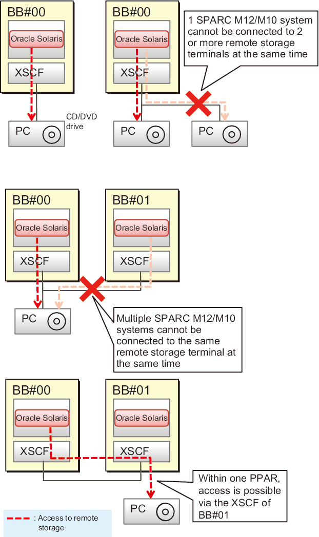
As shown in Figure 4-10, the SPARC M12/M10 chassis is connected to terminal (PC) media on a 1-to-1 basis. The same SPARC M12/M10 chassis cannot be connected to two or more terminals, and multiple SPARC M12/M10 chassis cannot be connected to the same terminal at the same time.
For a connection from the BB#00 logical domain to media in a terminal via the XSCF of BB#01, note that BB#00 and BB#01 must belong to the same physical partition.
|
Figure 4-10 Rules on Connection With a SPARC M12/M10 Chassis
|
|
As shown in Figure 4-11, in a system configuration with multiple SPARC M12-2S systems or multiple SPARC M10-4S systems, a terminal may be installed for each SPARC M12-2S/M10-4S system on a 1-to-1 basis. Of these installed terminals, multiple terminals can be connected at the same time. Likewise, in a configuration of physical partitions with multiple SPARC M12-2S systems or multiple /M10-4S systems, as many terminals as the number of configured chassis can be connected at the same time.
|
Figure 4-11 Forms of Simultaneous Connection for Multiple SPARC M12-2S or SPARC M10-4S Systems
|
|
Connection via a Slave XSCF
As shown in Figure 4-12, the remote storage of SPARC M12/M10 can even be connected via a slave XSCF.
| Note - The XSCF-LAN of the slave XSCF can be used only for remote storage. It cannot be used for services such as Telnet, SSH, XSCF Web, and SNMP. |
| Note - The XSCF-LAN of the slave crossbar box cannot be used for remote storage. |
|
Figure 4-12 Connection to Remote Storage via a Slave XSCF
|
|
| Note - If there is only one PC, you can even use the remote storage from each SPARC M12/M10 by switching the connecting SPARC M12/M10 system chassis each time. |
Before starting to configure remote storage
Before starting to configure remote storage, you need to have completed the network settings of the master/standby XSCF. This is because the XSCF must be rebooted when the master/standby XSCF network has been configured. Also, to make settings and perform operations from XSCF Web, the network settings of the master XSCF and the HTTPS service settings must already be done to enable the HTTPS service. This allows XSCF Web to be used.
For connection via a slave XSCF, you need to connect an XSCF-LAN cable and set the XSCF-LAN IP address. Also, for the network settings of the slave XSCF, configure remote storage from XSCF Web or the XSCF shell, not with the setnetwork command or the [Network] menu on the XSCF Web.
If the crossbar box is connected, the XSCF-LAN IP address of the SPARC M12/M10 (slave chassis) connected to the crossbar box must be set to prevent the XSCF-LAN of the crossbar box from being used for remote storage.
Table 4-2 lists XSCF network setting differences between using remote storage via the master/standby XSCF and using it via a slave XSCF.
| XSCF | XSCF-LAN Network Settings |
|---|---|
| SPARC M12/M10 chassis of master/standby XSCF | [Network] page of XSCF Web Alternatively, setnetwork, setroute, and applynetwork commands Note - An XSCF reboot is required. |
| SPARC M12/M10 chassis of slave XSCF | [Remote Storage] page of XSCF Web Alternatively, setremotestorage and showremotestorage commands Note - An XSCF reboot is not required. |
| Note - If no gateway is set in the routing settings, the terminal and XSCF-LAN must be connected in the same subnet. |
In a system configuration with multiple SPARC M12-2S systems or multiple SPARC M10-4S systems, the physical IP address is used as the XSCF-LAN IP address to access media in a terminal with remote storage. The takeover IP address (virtual address) is not used.
For details on the XSCF network settings, see "4.6.10 Configuring the XSCF-LAN Used with Remote Storage."
For details on the XSCF network settings, see "4.6.10 Configuring the XSCF-LAN Used with Remote Storage."
< Previous Page | Next Page >