9.6 Installing a PCI Express Cable
9.6 Installing a PCI Express Cable
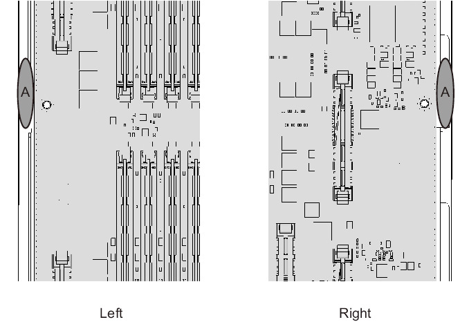
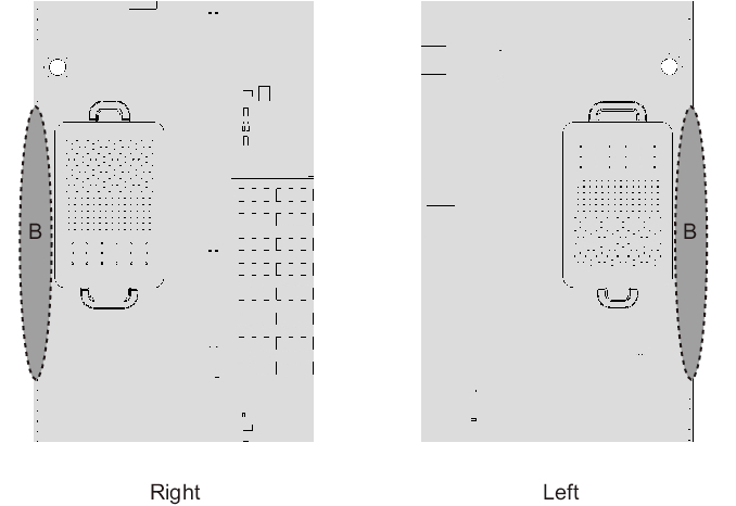
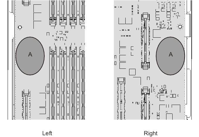
| Note - A part of the procedure varies depending on the CPU memory unit type. To determine the CPU memory unit type, check the label in Figure 9-2. |
Connect the CPU memory unit lower and CPU memory unit upper with a PCIe cable.
Before installing a CPU memory unit upper, confirm that PCIe cables are connected to the CPU memory unit lower.
If PCIe cables have not been connected to the CPU memory unit lower, remove the CPU memory unit board (lower) once, and connect PCIe cables.
If PCIe cables are connected to the CPU memory unit lower, this work is not required.
| Note - If PCIe cables have not been connected to the CPU memory unit lower when you are installing a CPU memory unit upper, use the PCIe cables supplied with the CPU memory unit upper. |
- Remove the eight screws from both sides of the XSCF cable connection ports on the rear of the CPU memory unit lower.
Use a flathead screwdriver (small) to remove them.
For the SPARC M10-4 with a FRAME-A CPU memory unit and the SPARC M10-4/M10-4S with a FRAME-B CPU memory unit, this step is not necessary.
|
Figure 9-18 Screws for both ends of the XSCF cable connection ports (for the SPARC M10-4S with a FRAME-A CPU memory unit)
|

|
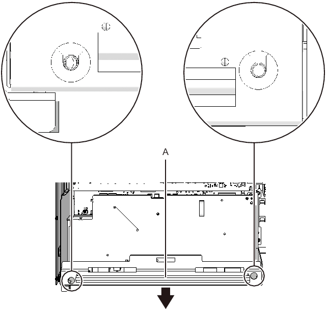
- Loosen the two screws holding the upper part of the rear of the CPU memory unit lower. Then, remove the rear cover (A in Figure 9-19) by pulling it in the direction of the arrow.
|
Figure 9-19 Removing the rear cover
|

|
- Remove and pull out the XSCF board.- For the SPARC M10-4 with a FRAME-A/FRAME-B CPU memory unit
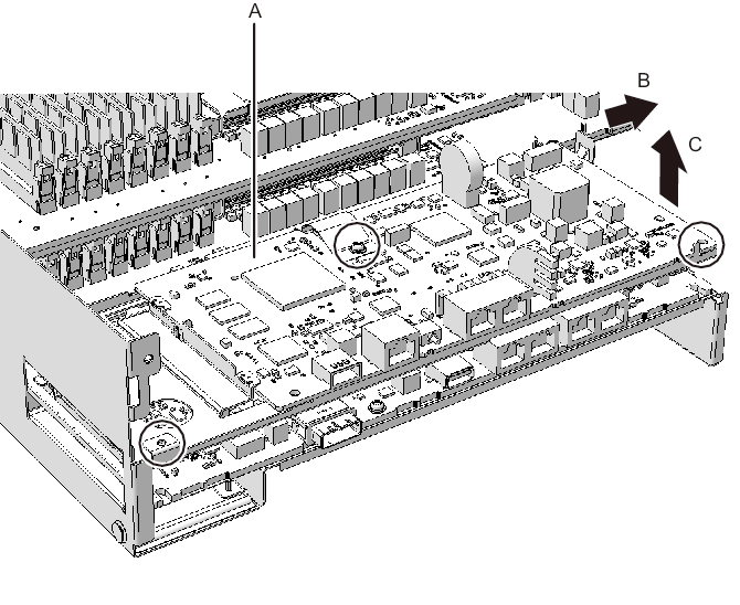
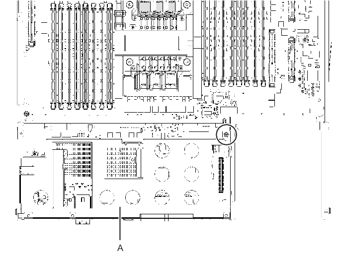
Remove the three screws securing the XSCF board (A in Figure 9-20) and rear cover. Tilt the right lever of the XSCF mount with your fingers by about 5 mm (0.2 in.) to the right (B in Figure 9-20). Lift the right side of the XSCF board to release the connection of the connector (C in Figure 9-20).
|
Figure 9-20 Releasing a connected XSCF board (for SPARC M10-4 with a FRAME-A CPU memory unit)
|
|
- - For the SPARC M10-4S with a FRAME-A/FRAME-B CPU memory unit
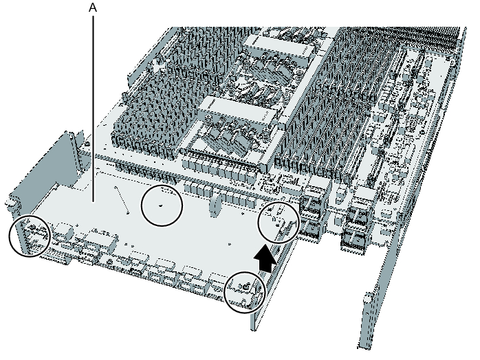
Remove the four screws securing the XSCF board (A in Figure 9-21). Then, lift the right side of the XSCF board to release the connection of the connector.
|
Figure 9-21 Releasing a connected XSCF board (for the SPARC M10-4S with a FRAME-A/FRAME-B CPU memory unit)
|
|
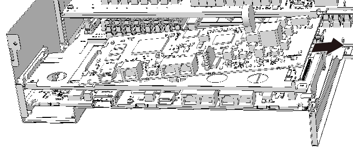
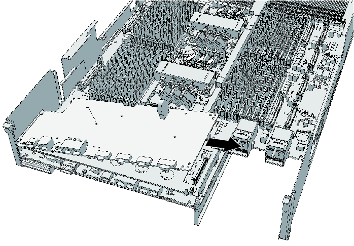
- Pull out the XSCF board diagonally to the right (arrow).
| Note - Place the removed XSCF board on a grounded antistatic ESD mat. |
|
Figure 9-22 Pulling out an XSCF board (for the SPARC M10-4 with a FRAME-A/FRAME-B CPU memory unit)
|
|
|
Figure 9-23 Pulling out an XSCF board (for the SPARC M10-4S with a FRAME-A/FRAME-B CPU memory unit)
|
|
- Remove the screw securing the XSCF mount.
- - For the SPARC M10-4/M10-4S with a FRAME-A CPU memory unit
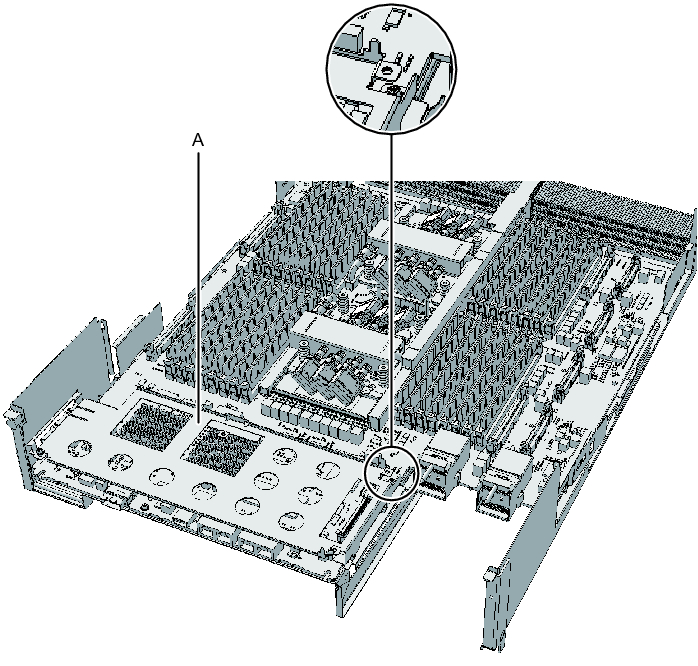
Remove the one screw securing the XSCF mount (A in Figure 9-24 and Figure 9-25).
|
Figure 9-24 Screw for the XSCF mount (for the SPARC M10-4 with a FRAME-A/FRAME-B CPU memory unit)
|
|
|
Figure 9-25 Screw for the XSCF mount (for the SPARC M10-4S with a FRAME-A CPU memory unit)
|
|
- - For the SPARC M10-4S with a FRAME-B CPU memory unit
Remove the two screws securing the XSCF mount (A in Figure 9-26).
|
Figure 9-26 Screw for the XSCF mount (for the SPARC M10-4S with a FRAME-B CPU memory unit)
|
|
- Remove the XSCF mount.
- - For the SPARC M10-4/M10-4S with a FRAME-A CPU memory unit
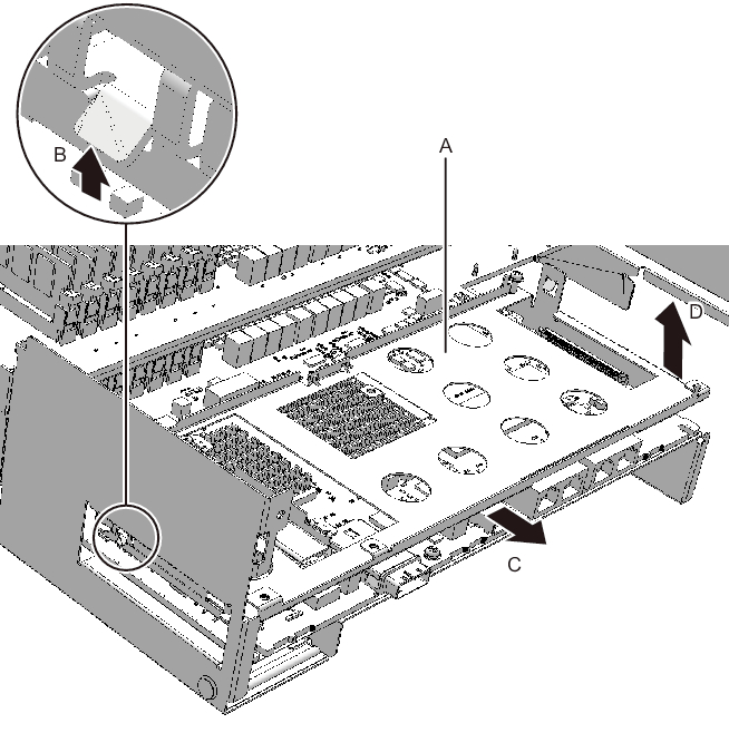
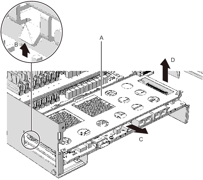
Lift the protruding left lever (B in Figure 9-27 and Figure 9-28) of the XSCF mount (A in Figure 9-27 and Figure 9-28) by about 2 mm (0.1 in.) with your fingers, and slide it about 8 mm (0.4 in.) toward the front (C in Figure 9-27 and Figure 9-28). Then, pull it upward to remove it (D in Figure 9-27 and Figure 9-28).
|
Figure 9-27 Removing the XSCF mount (for the SPARC M10-4 with a FRAME-A CPU memory unit)
|
|
|
Figure 9-28 Removing the XSCF mount (for the SPARC M10-4S with a FRAME-A CPU memory unit)
|
|
- - For the SPARC M10-4 with a FRAME-B CPU memory unit
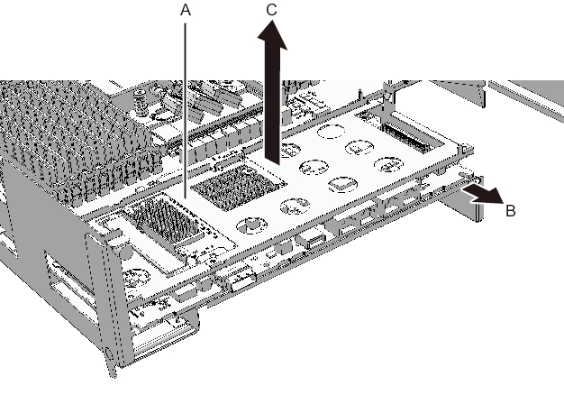
Slide the right side of the XSCF mount (A in Figure 9-29) by about 8 mm (0.4 in.) toward the front (B in Figure 9-29). Then, pull it upward to remove it (C in Figure 9-29).
|
Figure 9-29 Removing the XSCF mount (for the SPARC M10-4 with a FRAME-B CPU memory unit)
|
|
- - For the SPARC M10-4S with a FRAME-B CPU memory unit
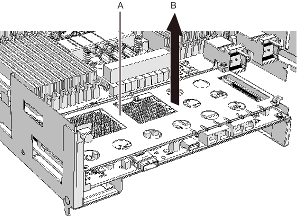
Pull the XSCF mount upward (A in Figure 9-30) to remove it (B in Figure 9-30).
|
Figure 9-30 Removing the XSCF mount (for the SPARC M10-4S with a FRAME-B CPU memory unit)
|
|
- Remove the screws securing the CPU memory unit board.
- - For the SPARC M10-4/M10-4S with a FRAME-A CPU memory unit
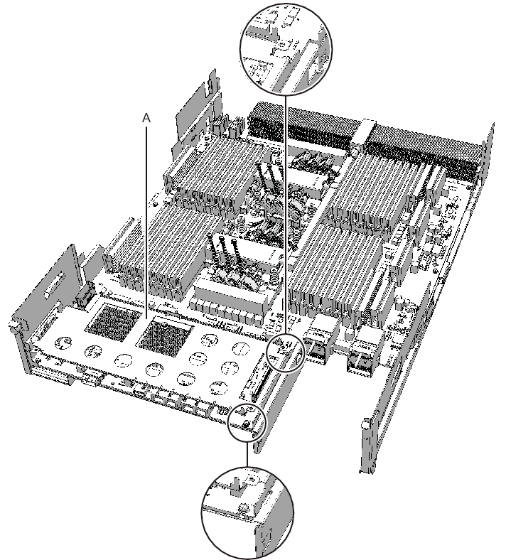
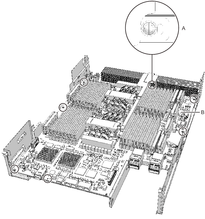
Remove the one black screw (A in Figure 9-31) securing the center part of the radiator on the front and the four screws securing the CPU memory unit board (B in Figure 9-31).
|
Figure 9-31 Screws on the CPU memory unit board (for the SPARC M10-4/M10-4S with a FRAME-A CPU memory unit)
|
|
- - For the SPARC M10-4/M10-4S with a FRAME-B CPU memory unit
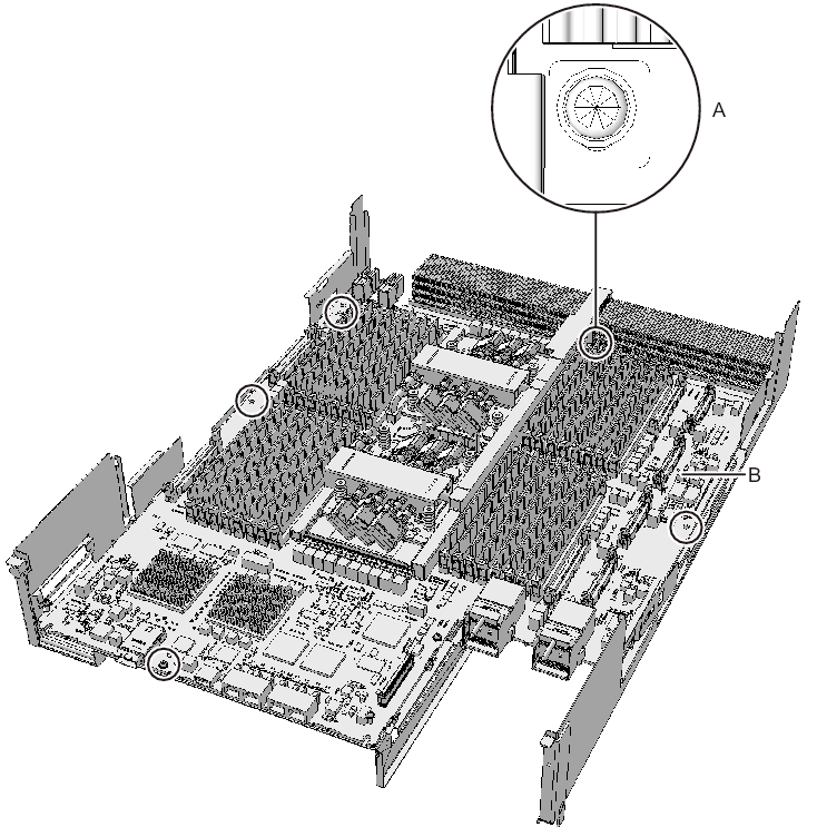
Remove the one black screw (A in Figure 9-32) securing the center part of the radiator on the front and the six screws securing the CPU memory unit board (B in Figure 9-32).
|
Figure 9-32 Screws on the CPU memory unit board (for the SPARC M10-4/M10-4S with a FRAME-B CPU memory unit)
|
|
- Place your thumbs on the frame, at the center on the right and left sides of the CPU memory unit board (A in Figure 9-33), and insert your fingers under the CPU memory unit board (B in Figure 9-34) from the sides of the connector unit.
| Note - Be careful not to touch or catch your clothes or wrist strap on a connector pin located on the back of the CPU memory unit board. |
| Note - Hard objects such as a machine tools should not come in contact with the connector located on the back side of the CPU memory unit board. |
|
Figure 9-33 Finger position when releasing the connection of the connector (surface)
|
|
|
Figure 9-34 Finger position when releasing the connection of the connector (back)
|
|
- Supporting the frame with your thumbs (A in Figure 9-35), disconnect the connector by pushing up the left and right sides at the same time with the fingers that are inserted under the CPU memory unit board (B in Figure 9-35).
|
Figure 9-35 How to disconnect the connector
|
|
- Place your thumbs on the connector unit at the center on the right and left sides of the CPU memory unit board (A in Figure 9-36) and hold the board by inserting your fingers under the CPU memory unit board (B in Figure 9-37) from the sides of the connector unit.
| Note - Place the removed CPU memory unit board on a grounded antistatic ESD mat. |
|
Figure 9-36 Finger position when holding the board (surface)
|
|
|
Figure 9-37 Finger position when holding the board (back)
|

|
- Lift the CPU memory unit board in the horizontal position, and remove it from the frame.
|
Figure 9-38 Removing the CPU memory unit board
|
|
- Remove the sheet (A in Figure 9-39).
You can expand the CPU memory unit upper by performing the above procedure. You do not have to perform step 13.
|
Figure 9-39 Removing the sheet
|

|
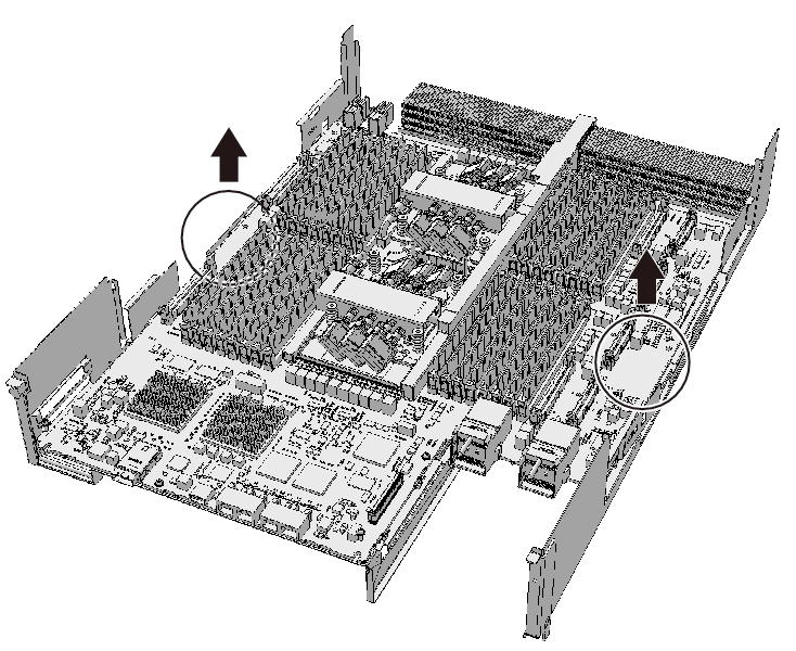
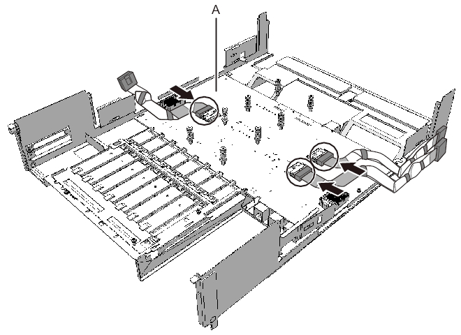
- Remove the three PCIe cables.
The direction in which the PCIe cables are removed varies depending on the type of the CPU memory unit.
|

- - The connectors for the three PCIe cables facing the outside of the CPU memory unit
|
Figure 9-40 Removing the PCIe cables (with the connectors for the three PCIe cables facing the outside of the CPU memory unit)
|
|
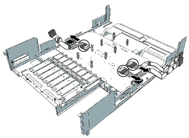
- The connector for one PCIe cable facing the outside of the CPU memory unit and the other two facing the front of the CPU memory unit
|
Figure 9-41 Removing the PCIe cables (with the connector for one PCIe cable facing the outside and the other two facing the front of the CPU memory unit)
|
|
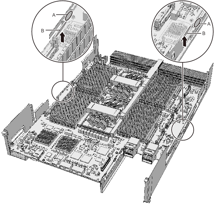
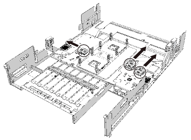
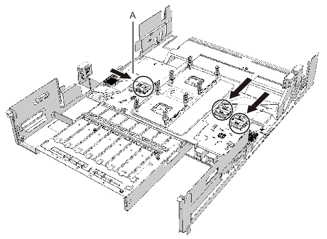
- Install the PCIe cables on the PCIBP board.
Connect the three PCIe cables by matching the PCIe cable position labels with the corresponding position marks on the PCIBP board (A in Figure 9-42 and Figure 9-43).
The direction in which the PCIe cables are installed varies depending on the type of the CPU memory unit.
|
| Note - Ensure that the PCIe cables are firmly connected and secure. |
- - The connectors for the three PCIe cables facing the outside of the CPU memory unit
|
Figure 9-42 Installing the PCIe cables (with the connectors for the three PCIe cables facing the outside of the CPU memory unit)
|
|
- - The connector for one PCIe cable facing the outside of the CPU memory unit and the other two facing the front of the CPU memory unit
|
Figure 9-43 Installing the PCIe cables (with the connector for one PCIe cable facing the outside and the two facing the front of the CPU memory unit)
|
|
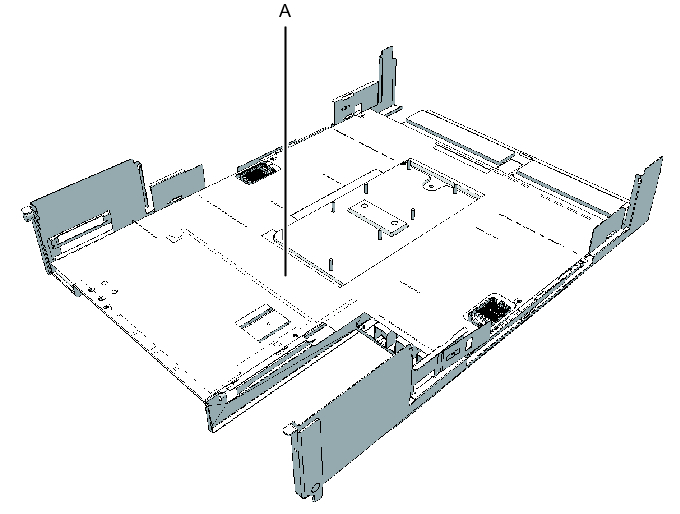
- Install the sheet (A in Figure 9-44).
|
Figure 9-44 Installing sheet
|
|
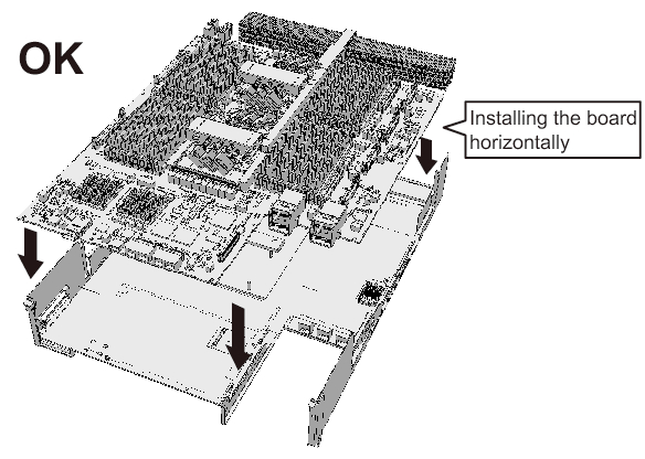
- Install the CPU memory unit board and secure it to the frame with screws.
Hold the connector unit at the center of the CPU memory unit board and install it on the frame in the horizontal position.
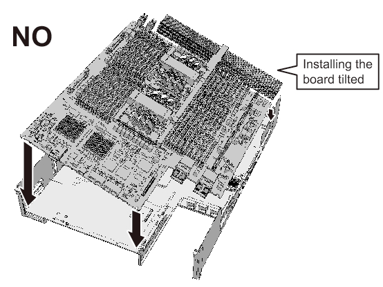
For how to hold the CPU memory unit board, see Figure 9-45 and Figure 9-46.
|
|
Figure 9-45 Correct position of the CPU memory unit board
|
|
|
Figure 9-46 Wrong position of the CPU memory unit board
|
|
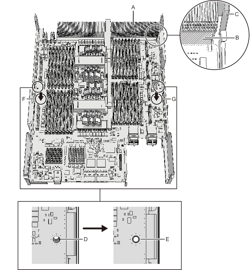
- - For the SPARC M10-4/M10-4S with a FRAME-A CPU memory unit
Install the board so that the bent tip of the frame (C in Figure 9-47) can be inserted into the space (B in Figure 9-47) between the end face on the far side of the CPU memory unit board and the radiator (A in Figure 9-47).
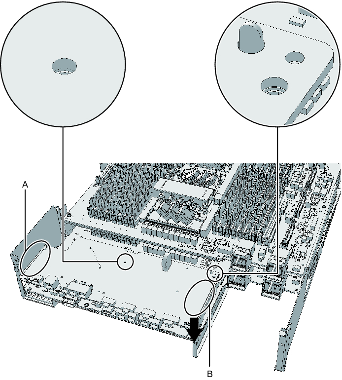
- a. Insert the board carefully into the frame, keeping it horizontal.b. If the threaded hole of the board and the threaded hole of the frame (D in Figure 9-47) do not match when you are inserting the board, place the board by adjusting the position of the board so that the outer circumference of the threaded hole of the frame is visible (E in Figure 9-47).c. Attach the connector by pressing down the connector units (F and G in Figure 9-47) at the center on the right and left sides of the board at the same time.
|
Figure 9-47 Installing the CPU memory unit board (for the SPARC M10-4/M10-4S with a FRAME-A CPU memory unit)
|
|
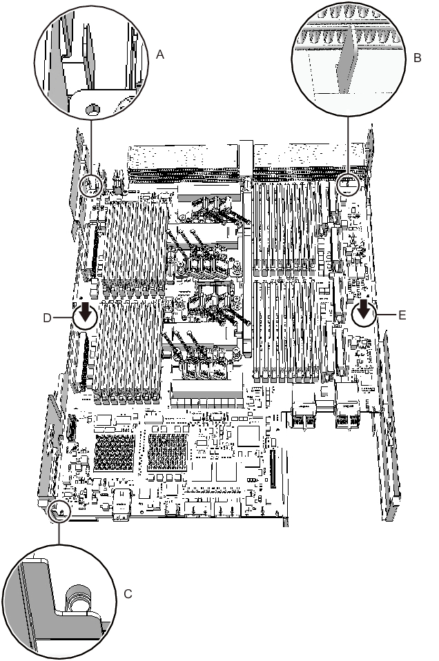
- - For the SPARC M10-4/M10-4S with a FRAME-B CPU memory unit
Install the CPU memory unit board, with the left and right guides (A and B in Figure 9-48) and the left guide on the board (C in Figure 9-48) as guides.
- a. Insert the board carefully into the frame, keeping it horizontal.b. Attach the connector by pressing down the connector units (D and E in Figure 9-48) at the center on the right and left sides of the board at the same time.
|
Figure 9-48 Installing the CPU memory unit board (for the SPARC M10-4/M10-4S with a FRAME-B CPU memory unit)
|
|
- Secure the CPU memory unit board with screws.- For the SPARC M10-4/M10-4S with a FRAME-A CPU memory unit
Secure the CPU memory unit board with four screws and the center part of the radiator on the front with one black screw.- For the SPARC M10-4/M10-4S with a FRAME-B CPU memory unit
Secure the CPU memory unit board with six screws.
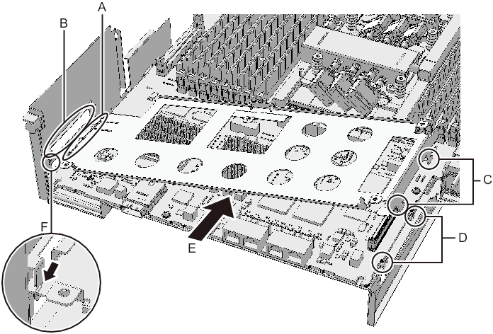
- Install the XSCF mount and secure it with screws.- For the SPARC M10-4/SPARC M10-4S with a FRAME-A CPU memory unit
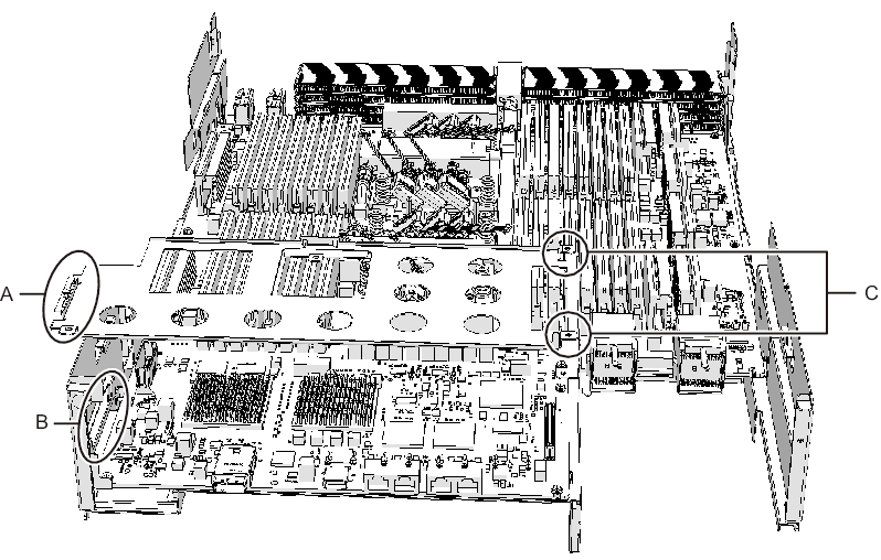
Insert the left side (A in Figure 9-49) of the XSCF mount into the opening (B in Figure 9-49) in the frame of the CPU memory unit lower. Next, insert the two guides (C in Figure 9-49) on the right side of the mount into the openings (D in Figure 9-49) in the frame. Then, install the XSCF mount by sliding it to the front (E in Figure 9-49) and securing it with one screw.
| Note - After sliding the XSCF mount to the front, confirm that the mount at part F in Figure 9-49 engages the frame guide. |
|
Figure 9-49 Installing the XSCF mount (for the SPARC M10-4/M10-4S with a FRAME-A CPU memory unit)
|
|
- - For the SPARC M10-4 with a FRAME-B CPU memory unit
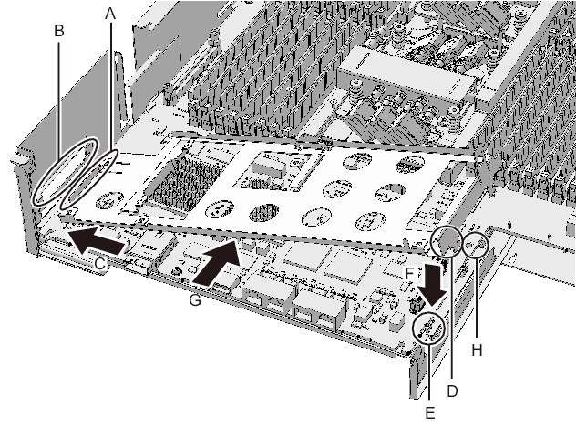
Insert the left protruding part (A in Figure 9-50) of the XSCF mount diagonally from above (C in Figure 9-50) into the opening (B in Figure 9-50) in the frame of the CPU memory unit lower. Next, insert the right protruding part (D in Figure 9-50) of the mount from above (F in Figure 9-50) into the opening (E in Figure 9-50) in the frame. Then, slide the XSCF mount to the front (G in Figure 9-50), and secure it with one screw (H in Figure 9-50).
|
Figure 9-50 Installing the XSCF mount (for the SPARC M10-4 with a FRAME-B CPU memory unit)
|
|
- - For the SPARC M10-4S with a FRAME-B CPU memory unit
Insert the left protruding part (A in Figure 9-51) of the XSCF mount from above into the opening (B in Figure 9-51) in the frame of the CPU memory unit lower. Then, secure it with two screws (C in Figure 9-51).
|
Figure 9-51 Installing the XSCF mount (for the SPARC M10-4S with a FRAME-B CPU memory unit)
|
|
- Install the XSCF board.- For the SPARC M10-4 with a FRAME-A/FRAME-B CPU memory unit
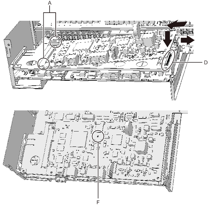
Insert the XSCF board into guides at two locations (A in Figure 9-52) on the mount (B in Figure 9-52), and push the right lever of the mount by about 5 mm (0.2 in.) to the right (C in Figure 9-52) to attach (E in Figure 9-52) the connector unit (D in Figure 9-52). Then, secure it with one screw (F in Figure 9-52).
|
Figure 9-52 Installing the XSCF board (for the SPARC M10-4 with a FRAME-A/FRAME-B CPU memory unit)
|
|
- - For the SPARC M10-4S with a FRAME-A/FRAME-B CPU memory unit
Insert the XSCF board into the left guide (A in Figure 9-53), and press down the right connector unit (B in Figure 9-53) to attach the connector. Then, secure it with two screws.
|
Figure 9-53 Installing the XSCF board (for the SPARC M10-4S with a FRAME-A/FRAME-B CPU memory unit)
|
|
- Attach the rear cover with two screws from the upper part of the rear of the CPU memory unit lower.
|
Figure 9-54 Screws for rear cover
|
|
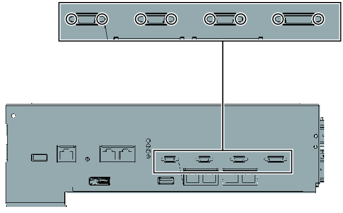
- Install the eight screws on both sides of the XSCF cable connection ports on the rear of the CPU memory unit lower.
For the SPARC M10-4 with a FRAME-A CPU memory unit and the SPARC M10-4/M10-4S with a FRAME-B CPU memory unit, this step is not necessary.
|
Figure 9-55 Screws for both ends of the XSCF cable connection ports (for the SPARC M10-4S with a FRAME-A CPU memory unit)
|
|
< Previous Page | Next Page >