7.2.1 Active replacement
7.2.1 Active replacement
This section describes the workflows for active/hot and active/cold FRU replacement. References to detailed descriptions are written in the work procedure tables. See any of them as required. You can perform active/cold replacement only for a system with a building block configuration.
Active replacement has the following patterns:
- Active/hot replacement (for a power supply unit or fan unit)
- Active/hot replacement (for an internal disk in a RAID configuration)
- Active/hot replacement (for an internal disk not in a RAID configuration)
- Active/hot replacement (for a PCI Express card)
- Active/cold replacement (building block configuration only)
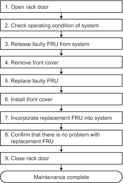
Active/hot replacement (for a power supply unit or fan unit)
Active/hot replacement can be performed on a power supply unit and a fan unit. Perform the following procedure to replace the unit.
|
Figure 7-2 Active/hot replacement flow (for a power supply unit or fan unit)
|
|
| Item | Work procedure | Reference |
|---|---|---|
| 1 | Opening the rack door | |
| 2 | Checking the operating condition of the system | "5.3.1 Checking the operating condition of the physical partition or logical domain" |
| 3 | Releasing a faulty FRU from the system | "5.8.2 Releasing of the power supply unit and fan unit of the SPARC M10-4/M10-4S" |
| 4 | Removing the front cover | "5.9.5 Removing the front cover" |
| 5 | Replacing a faulty FRU | "Chapter 12 Maintaining the Power Supply Units" "Chapter 11 Maintaining the Fan Units" |
| 6 | Installing the front cover | "6.1.5 Installing the front cover" |
| 7 | Incorporating the replacement FRU into the system | "6.2.2 Incorporation of the power supply unit and fan unit of the SPARC M10-4/M10-4S" |
| 8 | Confirming that there is no problem with the replacement FRU | "6.3.3 Checking the FRU status after maintenance" |
| 9 | Closing the rack door |
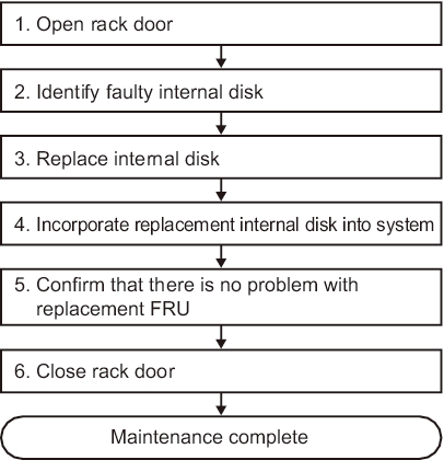
Active/hot replacement (for an internal disk in a RAID configuration)
Active/hot replacement can be performed on an internal disk. If the internal disk is in a RAID configuration, perform the following procedure to replace it.
|
Figure 7-3 Active/hot replacement flow (for an internal disk in a RAID configuration)
|
|
| Item |
Work procedure | Reference |
|---|---|---|
| 1 | Opening the rack door | |
| 2 | Identifying a faulty internal disk | "14.2.9 Checking for a Failed Disk Drive" in the Fujitsu SPARC M12 and Fujitsu M10/SPARC M10 System Operation and Administration Guide |
| 3 | Replacing a faulty internal disk | "Chapter 10 Maintaining the Internal Disks" |
| 4 | Incorporating the replacement internal disk into the system | "14.2.10 Replacing a Failed Disk Drive" in the Fujitsu SPARC M12 and Fujitsu M10/SPARC M10 System Operation and Administration Guide |
| 5 | Confirming that there is no problem with the replacement FRU | "6.3.3 Checking the FRU status after maintenance" |
| 6 | Closing the rack door |
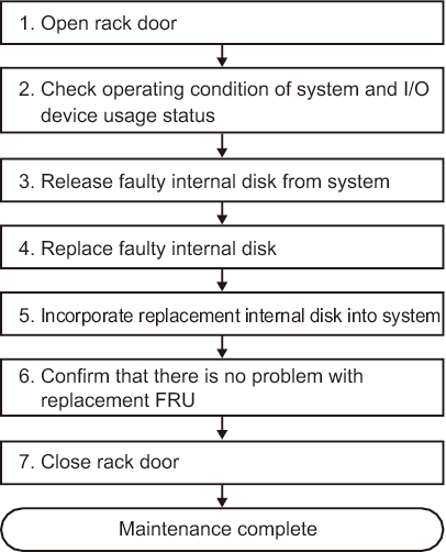
Active/hot replacement (for an internal disk not in a RAID configuration)
Active/hot replacement can be performed on an internal disk. If the internal disk is not in a RAID configuration, perform the following procedure to replace it.
|
Figure 7-4 Active/hot replacement flow (for an internal disk not in a RAID configuration)
|
|
| Item | Work procedure | Reference |
|---|---|---|
| 1 | Opening the rack door | |
| 2 | Checking the operating condition of the system and the I/O device usage status | "5.3 Checking the Operating Condition and Resource Usage Status" |
| 3 | Releasing a faulty internal disk from the system | "Enabling the removal of an internal disk" in "5.4.2 Enabling the removal of an I/O device" |
| 4 | Replacing a faulty internal disk | "Chapter 10 Maintaining the Internal Disks" |
| 5 | Incorporating the replacement internal disk | "6.5.2 Incorporating an I/O device" |
| 6 | Confirming that there is no problem with the replacement FRU | "6.3.3 Checking the FRU status after maintenance" |
| 7 | Closing the rack door |
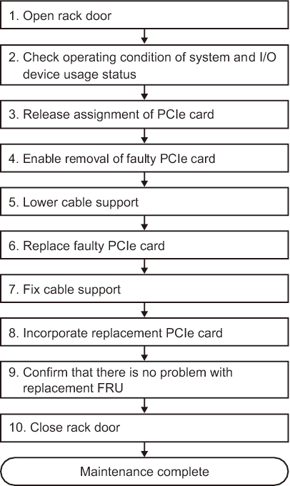
Active/hot replacement (for a PCI Express card)
Active/hot replacement can be performed on a PCI Express card. Perform the following procedure to replace the unit.
|
Figure 7-5 Active/hot replacement flow (for a PCI Express card)
|
|
| Item | Work procedure | Reference |
|---|---|---|
| 1 | Opening the rack door | |
| 2 | Checking the operating condition of the system and the I/O device usage status | "5.3 Checking the Operating Condition and Resource Usage Status" |
| 3 | Releasing the assignment of a PCIe card | "5.4.1 Releasing the assignment of I/O devices" |
| 4 | Enabling the removal of a faulty PCIe card | "5.4.2 Enabling the removal of an I/O device" |
| 5 | Lowering the cable support | "5.9.2 Lowering the cable support" |
| 6 | Replacing a faulty PCIe card | "Chapter 8 Maintaining the PCI Express Cards" |
| 7 | Fixing the cable support | "6.1.2 Fixing the cable support" |
| 8 | Incorporating the replacement PCIe card | "6.5.2 Incorporating an I/O device" |
| 9 | Confirming that there is no problem with the replacement FRU | "6.3.3 Checking the FRU status after maintenance" |
| 10 | Closing the rack door |
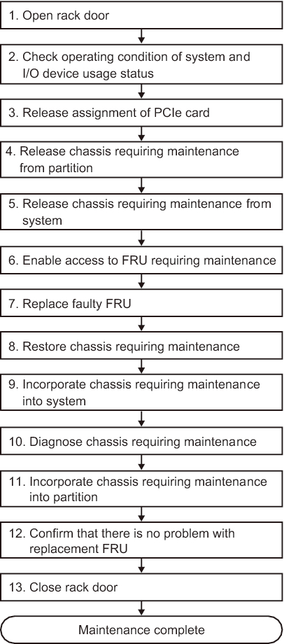
Active/cold replacement (building block configuration only)
Active/cold replacement can be performed on each FRU in a building block configuration. Perform the following procedure to replace the unit.
|
Figure 7-6 Active/cold replacement flow (building block configuration only)
|
|
| Item | Work procedure | Reference |
|---|---|---|
| 1 | Opening the rack door | |
| 2 | Checking the operating condition of the system and the I/O device usage status | "5.3 Checking the Operating Condition and Resource Usage Status" |
| 3 | Releasing the assignment of a PCIe card | "5.4.1 Releasing the assignment of I/O devices" |
| 4 | Releasing the chassis requiring maintenance from the partition | "5.4.3 Releasing a chassis requiring maintenance from the physical partition" |
| 5 | Releasing the chassis requiring maintenance from the system | "5.8.1 Releasing of the SPARC M10-4S chassis (possible only in a system with a building block configuration)" |
| 6 | Enabling access to the FRU requiring maintenance | "5.9 Accessing a FRU" |
| 7 | Replacing a faulty FRU | See the removal and installation procedures in the maintenance procedures for each FRU. "Chapter 8 Maintaining the PCI Express Cards" "Chapter 9 Maintaining the CPU Memory Unit/Memory" (*1)(*2) "Chapter 10 Maintaining the Internal Disks" "Chapter 11 Maintaining the Fan Units" "Chapter 12 Maintaining the Power Supply Units" "Chapter 13 Maintaining the PSU Backplane Unit/Operation Panel" (*1) "Chapter 16 Maintaining the XSCF BB Control Cables" "Chapter 17 Maintaining the XSCF DUAL Control Cables" |
| 8 | Restoring the chassis requiring maintenance | "6.1 Restoring the Chassis" |
| 9 | Incorporating the chassis requiring maintenance into the system | "6.2.1 Incorporation of the SPARC M10-4S chassis (possible only in a system with a building block configuration)" |
| 10 | Diagnosing the chassis requiring maintenance | "6.3.1 Diagnosing the system board" (*3) "6.3.2 Diagnosing the crossbar unit and crossbar cables" |
| 11 | Incorporating the chassis requiring maintenance into a partition | "6.5.1 Incorporating a chassis into a physical partition" |
| 12 | Confirming that there is no problem with the replacement FRU | "6.3.3 Checking the FRU status after maintenance" |
| 13 | Closing the rack door | |
| *1 Simultaneous replacement of the CPU memory unit and PSU backplane unit is prohibited. To replace the CPU memory unit and PSU backplane unit, first replace either of the units and perform the work in "9. Incorporating the chassis requiring maintenance into the system." Then, return to "5. Releasing the chassis requiring maintenance from the system," and replace the other unit. Lastly, restore the system. *2 If a CPU memory unit lower is replaced in the system of the hardware RAID volume in a hardware RAID configuration using internal disks, you need to reactivate the hardware RAID volume before starting Oracle Solaris. Start Oracle Solaris on the control domain as described in "11. Incorporating the chassis requiring maintenance into a partition." For details, see "14.2.11 Re-enabling a Hardware RAID Volume" in the Fujitsu SPARC M12 and Fujitsu M10/SPARC M10 System Operation and Administration Guide. *3 Normally, the testsb command is executed during replacefru command processing. However, if that is canceled, diagnose the system board before incorporating the chassis requiring maintenance into the physical partition. |
||
< Previous Page | Next Page >