7.3.3 System-stopped addition
7.3.3 System-stopped addition
This section describes the workflows for system-stopped/hot and system-stopped/cold FRU installation. References to detailed descriptions are written in the workflow. See any of them as required.
System-stopped addition has the following patterns:
System-stopped/hot addition (for an internal disk or PCIe card)
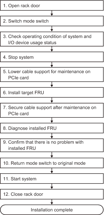
System-stopped/hot addition can be performed on a PCI Express card and an internal disk. Perform the following procedure to install the unit.
|
Figure 7-20 System-stopped/hot addition flow (for an internal disk or PCIe card)
|
|
| Item | Work procedure | Reference |
|---|---|---|
| 1 | Opening the rack door | |
| 2 | Switching the mode switch on the operation panel to Service mode | "5.2 Switching the Mode Switch to Service Mode" |
| 3 | Checking the operating condition of the system and the I/O device usage status | "5.3 Checking the Operating Condition and Resource Usage Status" |
| 4 | Stopping the system | "5.6 Stopping the Entire System" |
| 5 | Lowering the cable support for maintenance on a PCIe card | "5.9.2 Lowering the cable support" |
| 6 | Installing the target FRU | See the installation procedures for each FRU. "8.3 FRU Removal and Installation Flow" "10.3 FRU Removal and Installation Flow" |
| 7 | Securing the cable support after maintenance on a PCIe card | "6.1.2 Fixing the cable support" |
| 8 | Diagnosing the installed FRU | "6.3.1 Diagnosing the system board" |
| 9 | Confirming that there is no problem with the installed FRU | "6.3.3 Checking the FRU status after maintenance" |
| 10 | Returning the mode switch on the operation panel to Locked mode | "6.6 Returning the Mode Switch to Locked Mode" |
| 11 | Starting the system | "6.8 Starting the Entire System" |
| 12 | Closing the rack door |
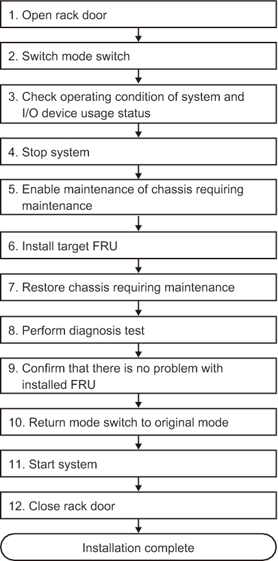
System-stopped/cold addition (for a single-chassis configuration)
System-stopped/cold addition can be performed on the CPU memory unit upper, a PCI Express card, memory, and an internal disk in a single-chassis configuration. Perform the following procedure to install the unit.
|
Figure 7-21 System-stopped/cold addition flow (for a single-chassis configuration)
|
|
| Item | Work procedure | Reference |
|---|---|---|
| 1 | Opening the rack door | |
| 2 | Switching the mode switch on the operation panel to Service mode | "5.2 Switching the Mode Switch to Service Mode" |
| 3 | Checking the operating condition of the system and the I/O device usage status | "5.3 Checking the Operating Condition and Resource Usage Status" |
| 4 | Stopping the system | "5.6 Stopping the Entire System" |
| 5 | Enabling maintenance of the chassis requiring maintenance | "5.9 Accessing a FRU" |
| 6 | Installing the target FRU | See the installation procedures for each FRU. "8.3 FRU Removal and Installation Flow" "9.4 FRU Removal and Installation Flow" "10.3 FRU Removal and Installation Flow" |
| 7 | Restoring the chassis requiring maintenance | "6.1 Restoring the Chassis" |
| 8 | Performing a diagnosis test | "6.3.1 Diagnosing the system board" |
| 9 | Confirming that there is no problem with the installed FRU | "6.3.3 Checking the FRU status after maintenance" |
| 10 | Returning the mode switch on the operation panel to Locked mode | "6.6 Returning the Mode Switch to Locked Mode" |
| 11 | Starting the system | "6.8 Starting the Entire System" |
| 12 | Closing the rack door |
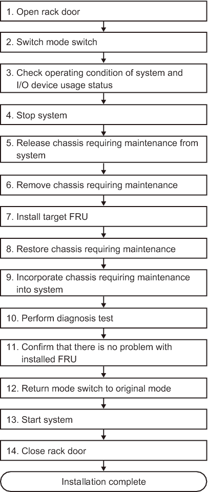
System-stopped/cold addition (for a building block configuration)
System-stopped/cold addition can be performed on the CPU memory unit upper, a PCI Express card, memory, and an internal disk in a building block configuration. Perform the following procedure to install the unit.
|
Figure 7-22 System-stopped/cold addition flow (for a building block configuration)
|
|
| Item | Work procedure | Reference |
|---|---|---|
| 1 | Opening the rack door | |
| 2 | Switching the mode switch on the operation panel to Service mode | "5.2 Switching the Mode Switch to Service Mode" |
| 3 | Checking the operating condition of the system and the I/O device usage status | "5.3 Checking the Operating Condition and Resource Usage Status" |
| 4 | Stopping the system | "5.6 Stopping the Entire System" |
| 5 | Releasing the chassis requiring maintenance from the system | "5.8.1 Releasing of the SPARC M10-4S chassis (possible only in a system with a building block configuration)" |
| 6 | Removing the chassis requiring maintenance | "5.9 Accessing a FRU" |
| 7 | Installing the target FRU | See the installation procedures for each FRU. "8.3 FRU Removal and Installation Flow" "9.4 FRU Removal and Installation Flow" "10.3 FRU Removal and Installation Flow" |
| 8 | Restoring the chassis requiring maintenance | "6.1 Restoring the Chassis" |
| 9 | Incorporating the chassis requiring maintenance into the system | "6.2.1 Incorporation of the SPARC M10-4S chassis (possible only in a system with a building block configuration)" |
| 10 | Performing a diagnosis test | "6.3.1 Diagnosing the system board" (*1) "6.3.2 Diagnosing the crossbar unit and crossbar cables" |
| 11 | Confirming that there is no problem with the installed FRU | "6.3.3 Checking the FRU status after maintenance" |
| 12 | Returning the mode switch on the operation panel to Locked mode | "6.6 Returning the Mode Switch to Locked Mode" |
| 13 | Starting the system | "6.8 Starting the Entire System" |
| 14 | Closing the rack door | |
| *1 The testsb command is executed during replacefru command processing. However, if that is canceled, diagnose the system board before incorporating the chassis requiring maintenance into the physical partition. | ||
< Previous Page | Next Page >