5.9.1 Removing the crossbar cables from the cable support
5.9.1 Removing the crossbar cables from the cable support
Perform these operations when the SPARC M10-4S has a building block configuration and when maintaining any of the following FRUs:
- CPU memory unit
- Memory
- PSU backplane unit
- Operation panel
- Remove the crossbar cables from the cable support.
Perform this procedure only when using equipment rack model 26xx or equipment rack model 16xx. The procedure may vary depending on the model of the equipment rack.
If you are not using 19-inch rack model 26xx or 19-inch rack model 16xx, this work is not required.
- Procedure when equipment rack model 26xx is used
- a. Remove all the crossbar cables from the crossbar unit.
| Note - Record the positions of the cables before removing them to ensure that they are reinstalled correctly. |
- b. Remove the hook-and-loop fastener (A in the figure) of the cable support, securing the crossbar cables.
|
Figure 5-1 Hook-and-loop fastener of the cable support
|

|
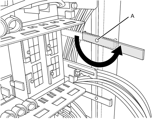
- c. Remove the screw securing the cable holder (A in Figure 5-2) that is fixed to the supporting column at the rear of the rack. Then, install the cable holder by rotating it 180 degrees.
|
Figure 5-2 Cable holder screw
|
|
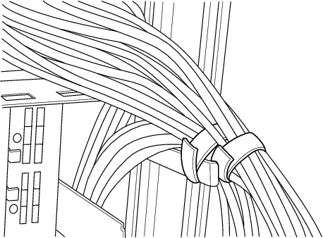
- d. Use the hook-and-loop fastener to secure the crossbar cables to the cable holder.
|
Figure 5-3 Fixing crossbar cables
|
|
- Procedure when equipment rack model 16xx is used
- a. Remove all the crossbar cables from the crossbar unit.
| Note - Record the positions of the cables before removing them to ensure that they are reinstalled correctly. |
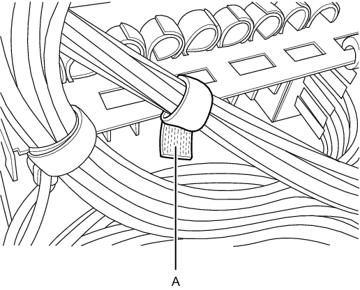
- b. Remove the hook-and-loop fastener (A in Figure 5-4) of the cable support, securing the crossbar cables.
|
Figure 5-4 Hook-and-loop fastener of the cable support
|
|
- c. Use the hook-and-loop fastener to secure the crossbar cables to the cable holder installed on the supporting column at the rear of the rack.
|
Figure 5-5 Fixing crossbar cables
|

|
< Previous Page | Next Page >