
2.1 Identifying the Names and Locations of Components
2.1 Identifying the Names and Locations of Components
This section describes the names and locations of the components mounted in the SPARC M10-4/M10-4S.
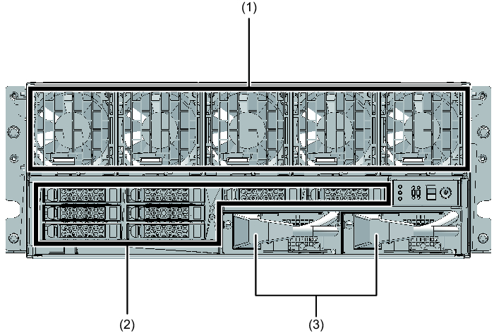
Components that can be accessed from the front
You can access the fan unit and power supply unit only after removing the front cover.
|
Figure 2-1 Locations of components that can be accessed from the front
|
|
| Location number | Component |
|---|---|
| 1 | Fan unit |
| 2 | Internal disk |
| 3 | Power supply unit |
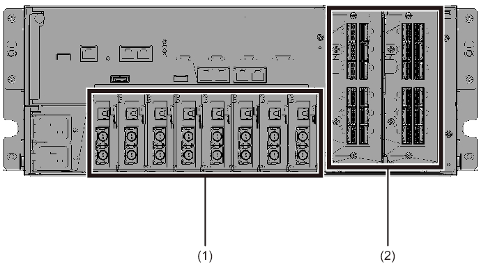
Components that can be accessed from the rear
|
Figure 2-2 Locations of components that can be accessed from the rear
|
|
| Location number | Component |
|---|---|
| 1 | PCI-Express (PCIe) card cassette |
| 2 | Crossbar unit (Only for the SPARC M10-4S. The SPARC M10-4 incorporates three PCIe card cassettes.) |
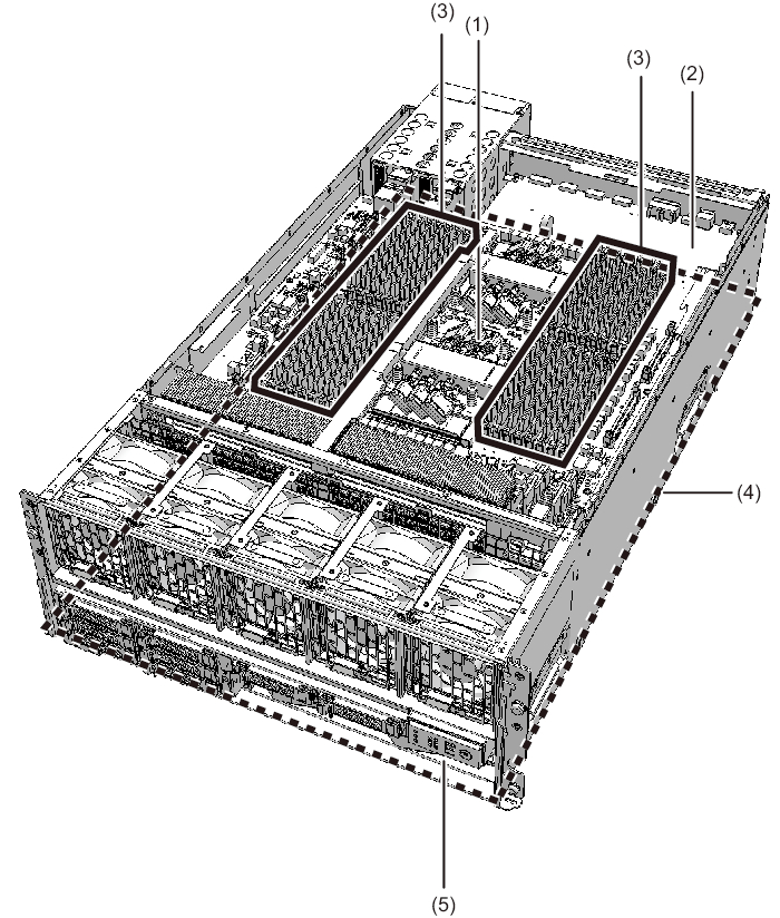
Internal components
To access internal components, remove the CPU memory unit from the chassis.
|
Figure 2-3 Locations of internal components
|
|
|
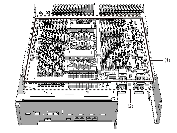
Figure 2-4 CPU memory unit removed from the chassis
|
|
| Location number | Component |
|---|---|
| 1 | CPU memory unit upper |
| 2 | CPU memory unit lower |
| 3 | Memory (CPU memory unit upper) |
| 4 | PSU backplane unit |
| 5 | Operation panel |
| Note - Two CPUs are directly installed on each of the CPU memory unit upper and CPU memory unit lower. Thus you cannot replace the CPUs individually. |
< Previous Page | Next Page >