2.3 Confirming the Functions of the Operation Panel
2.3 Confirming the Functions of the Operation Panel
This section describes the functions of the operation panel mounted on the SPARC M10-4/M10-4S.
The operation panel provides the system's display and control functions. The field engineer and system administrator can specify the operation mode or control start/stop of the system while checking the LEDs indicating the system operation status.
The operation panel provides the system's display and control functions. The field engineer and system administrator can specify the operation mode or control start/stop of the system while checking the LEDs indicating the system operation status.
| Note - In a building block configuration with a crossbar box connected, only the operation panel of the crossbar box that is the master XSCF can have all the operation panel functions enabled. |
|
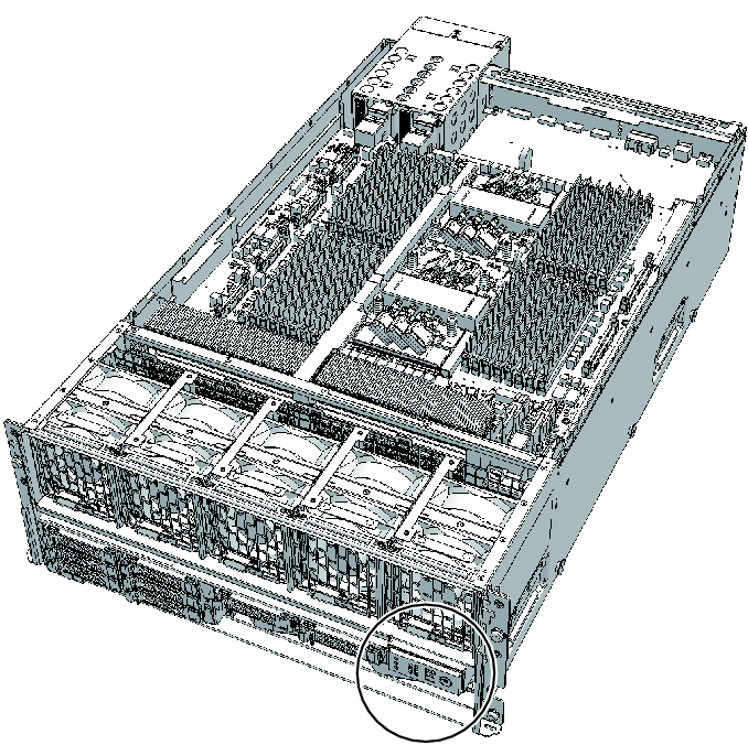
Figure 2-7 Location of the operation panel
|
|
|
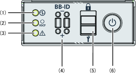
Figure 2-8 Appearance of operation panel
|
|
| Location number | LED/switch |
|---|---|
| 1 | POWER LED |
| 2 | XSCF STANDBY LED |
| 3 | CHECK LED |
| 4 | BB-ID switch (SPARC M10-4S only) |
| 5 | Mode switch |
| 6 | Power switch |
For a building block configuration, an operation panel is mounted in each chassis of the SPARC M10-4S. However, the only operation panel on which all of the LEDs and switches are enabled is that of the chassis housing the master XSCF.
Table 2-4 shows the display and operation status of the operation panel.
Table 2-4 shows the display and operation status of the operation panel.
| LEDs/switches on operation panel |
SPARC M10-4S is master XSCF | SPARC M10-4S is not master XSCF |
|---|---|---|
| POWER LED | Enabled (Indicates the start/stop state of the SPARC M10-4S) | Enabled (Indicates the start/stop state of the SPARC M10-4S) |
| XSCF STANDBY LED |
Enabled (Displays the XSCF status of the system) | Enabled (Displays the XSCF status of the SPARC M10-4S) |
| CHECK LED | Enabled (Indicates the SPARC M10-4S error state) | Enabled (Indicates the SPARC M10-4S error state) |
| BB-ID switch | Enabled (Registers a BB-ID number) | Enabled (Registers a BB-ID number) |
| Mode switch (*1) | Enabled (Mode operation of the system) | Disabled |
| Power switch | Enabled (Start/stop operation of the system) | Disabled |
| *1 Set the same mode for the SPARC M10-4S systems with the master XSCF and the XSCF in the standby state. If the settings are different, an asterisk (*) is displayed beside the components in the output of the showhardconf or showstatus command. | ||
< Previous Page | Next Page >