13.4 FRU Removal and Installation Flow
13.4 FRU Removal and Installation Flow
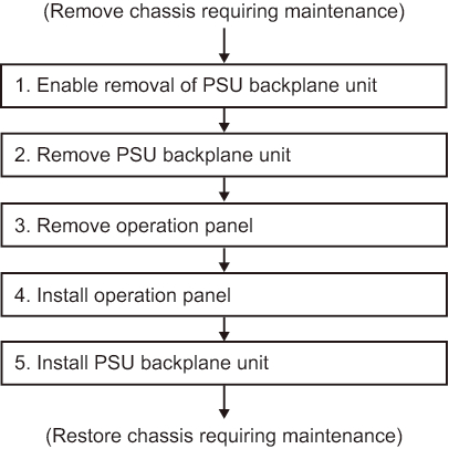
Perform maintenance work on the PSU backplane unit and operation panel by following the procedures shown in Figure 13-3 and Table 13-1.
The workflow assumes that the chassis requiring maintenance has been removed in "7.2 FRU Replacement Workflow."
The workflow assumes that the chassis requiring maintenance has been removed in "7.2 FRU Replacement Workflow."
|
Figure 13-3 Maintenance workflow
|
|
| Item | Maintenance work procedure | Reference |
|---|---|---|
| 1 | Accessing a CPU memory unit | 9.5.1 Accessing a CPU memory unit |
| 2 | Removing a CPU memory unit from the chassis | 9.5.2 Removing a CPU memory unit from the chassis |
| 3 | Removing an internal disk | 10.4 Removing an Internal Disk |
| 4 | Removing all the fan units | 11.3 Removing a Fan Unit |
| 5 | Removing a power supply unit | 12.3 Removing a Power Supply Unit |
| 6 | Removing the PSU backplane unit | 13.5.1 Removing the PSU backplane unit |
| 7 | Removing the operation panel | 13.5.2 Removing the operation panel |
| 8 | Installing the operation panel | 13.6.1 Installing the operation panel |
| 9 | Installing the PSU backplane unit | 13.6.2 Installing the PSU backplane unit |
| 10 | Installing a power supply unit | 12.4 Installing a Power Supply Unit |
| 11 | Installing all the fan units | 11.4 Installing a Fan Unit |
| 12 | Installing an internal disk | 10.5 Installing an Internal Disk |
| 13 | Installing the CPU memory unit in the chassis | 9.10.2 Installing the CPU memory unit in the chassis |
< Previous Page | Next Page >