9.5.1 Accessing a CPU memory unit
9.5.1 Accessing a CPU memory unit
- For a building block configuration of the SPARC M10-4S, remove the crossbar cables from the cable support.
For details, see "5.9.1 Removing the crossbar cables from the cable support." - Lower the cable support.
For details, see "5.9.2 Lowering the cable support." - Remove all the cables connected to the external interfaces on the rear of the chassis.
The cables to be removed are as follows.▪ Interface cable connected to the PCI Express (PCIe) card▪ Crossbar cables (They may have been removed in step 1.)▪ XSCF BB control cable (only for a building block configuration of the SPARC M10-4S)▪ XSCF DUAL control cable (only for a building block configuration of the SPARC M10-4S)▪ XSCF-LAN cable▪ Serial cable▪ LAN cable▪ SAS cable▪ USB cable
| Note - Record the positions of the cables before removing them to ensure that they are reinstalled correctly. |
- Remove all the PCIe card cassettes.
For details, see "8.4.1 Removing a PCI Express card cassette."
| Note - Make a note of the locations of the PCIe card cassettes before removing them to ensure that they are reinstalled correctly. |
- If any crossbar units are mounted, remove them.
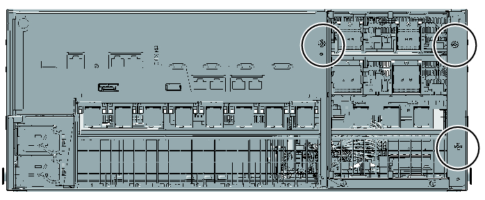
For details, see "15.3 Removing a Crossbar Unit." - Loosen the three screws holding the mounting frame and then remove it.
|
Figure 9-5 Screws securing the mounting frame
|
|
< Previous Page | Next Page >