2.4.3 LEDs on each component
2.4.3 LEDs on each component
Each component of the SPARC M10-4/M10-4S has a mounted LED. If a component experiences an error, check the LEDs to see which component requires maintenance. Check the LEDs before starting maintenance work.
The LEDs on each component and the states that they indicate are as follows.
The LEDs on each component and the states that they indicate are as follows.
|
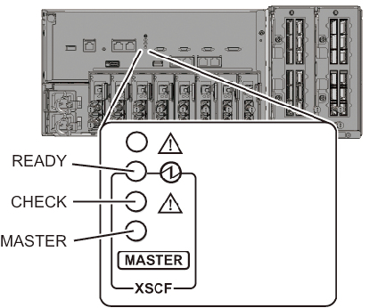
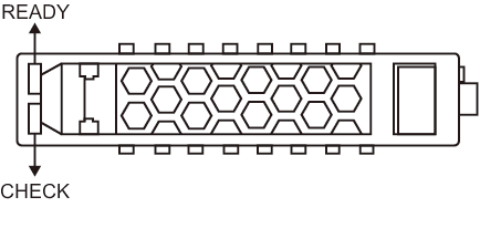
Figure 2-12 Locations of XSCF LEDs
|
|
| Name | Color | State | Description |
|---|---|---|---|
| READY | Green | On | The XSCF is running. |
| Blinking | The XSCF is being started. | ||
| Off | The XSCF is stopped. Alternatively, it has been disconnected from the building block configuration. | ||
| CHECK | Amber | On | Indicates that an error has occurred. Normal if the LED is turned off after it is on for a few seconds when the power is turned on |
| Off | Indicates the normal state. | ||
| MASTER (SPARC M10-4S only) |
Green | On | Master chassis |
| Off | The XSCF is in the state of being started. Alternatively, the XSCF is in the standby state or operating as a slave XSCF. |
|
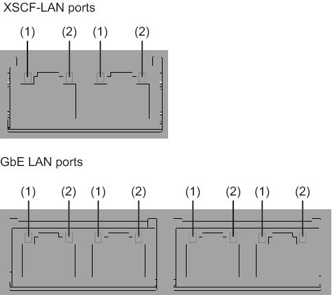
Figure 2-13 Locations of LAN port LEDs
|
|
| Location number | Name | Color | Status | Description |
|---|---|---|---|---|
| 1 | LINK SPEED | Amber | On | Indicates that the communication speed is 1 Gbps. |
| Green | On | Indicates that the communication speed is 100 Mbps. | ||
| Off | Indicates that the communication speed is 10 Mbps. | |||
| 2 | ACT | Green | Blinking | Indicates that communication is being performed. |
| Off | Indicates that communication is not being performed. |
|
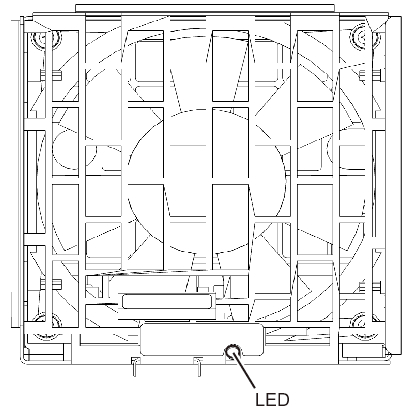
Figure 2-14 Location of the fan unit LED
|
|
| Name | Color | State | Description |
|---|---|---|---|
| CHECK | Amber | On | Indicates that an error has occurred. |
| Blinking | Indicates that the component requires maintenance. (This function is also referred to as the locator.) |
||
| Off | Indicates the normal state. |
|
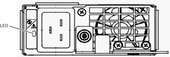
Figure 2-15 Location of the power supply unit LED
|
|
| Name | Color | State | Description |
|---|---|---|---|
| CHECK | Green | On | Indicates that the input power is turned on and being supplied normally. |
 /
/
|
Blinking | Indicates that the input power is being disconnected. | |
| Amber | On | Indicates that an error has occurred. Indicates that the input power to this power supply unit is turned off in redundant operation. |
|
| Blinking | Indicates the warning status (an error has occurred but the power supply unit is operating). | ||
| Off | Indicates that power is not being supplied. |
|
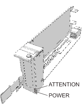
Figure 2-16 Locations of PCIe card slot LEDs
|
|
| Name | Color | State | Description |
|---|---|---|---|
| POWER | Green | On | Indicates that power is being supplied. |
| Off | Indicates that power is not being supplied. | ||
| ATTENTION | Amber | On | Indicates that an error has occurred. |
| Blinking | Indicates that the component requires maintenance. (This function is also referred to as the locator.) |
||
| Off | Indicates the normal state. |
|
Figure 2-17 Locations of internal disk LEDs
|
|
| Name | Color | State | Description |
|---|---|---|---|
| READY | Green | Blinking | Indicates that the disk is being accessed. This LED is normally on, but it blinks while the disk is being accessed. While the LED is blinking, maintenance such as removal of the disk cannot be performed. |
| Off | Indicates that maintenance such as removal of the disk can be performed. | ||
| CHECK | Amber | On | Indicates that an error has occurred. |
| Blinking | Indicates that the component requires maintenance. (This function is also referred to as the locator.) |
||
| Off | Indicates the normal state. |
< Previous Page | Next Page >