7.2.3 System-stopped replacement
7.2.3 System-stopped replacement
This section describes the workflows for system-stopped/hot and system-stopped/cold FRU replacement. References to detailed descriptions are written in the workflow. See any of them as required.
System-stopped replacement has the following patterns:
- System-stopped/hot replacement (for a power supply unit or fan unit)
- System-stopped/hot replacement (for an internal disk or PCIe card)
- System-stopped/cold replacement (for a single-chassis configuration)
- System-stopped/cold replacement (for a building block configuration)
- System-stopped/all power-off cold replacement (for a building block configuration)
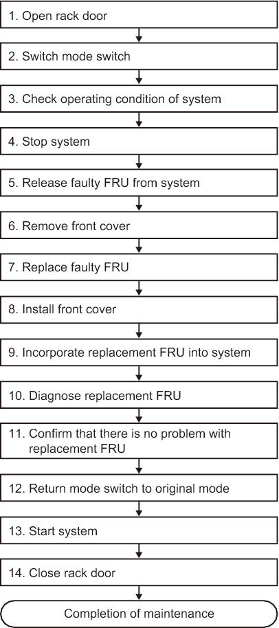
System-stopped/hot replacement (for a power supply unit or fan unit)
System-stopped/hot replacement can be performed on a power supply unit and a fan unit. Perform the following procedure to replace the unit.
|
Figure 7-10 System-stopped/hot replacement flow (for a power supply unit or fan unit)
|
|
| Item | Work procedure | Reference |
|---|---|---|
| 1 | Opening the rack door | |
| 2 | Switching the mode switch on the operation panel to Service mode | "5.2 Switching the Mode Switch to Service Mode" |
| 3 | Checking the operating condition of the system | "5.3 Checking the Operating Condition and Resource Usage Status" |
| 4 | Stopping the system | "5.6 Stopping the Entire System" |
| 5 | Releasing a faulty FRU from the system | "5.8.2 Releasing of the power supply unit and fan unit of the SPARC M10-4/M10-4S" |
| 6 | Removing the front cover | "5.9.5 Removing the front cover" |
| 7 | Replacing a faulty FRU | "Chapter 11 Maintaining the Fan Units" "Chapter 12 Maintaining the Power Supply Units" |
| 8 | Installing the front cover | "6.1.5 Installing the front cover" |
| 9 | Incorporating the replacement FRU into the system | "6.2.2 Incorporation of the power supply unit and fan unit of the SPARC M10-4/M10-4S" |
| 10 | Diagnosing the replacement FRU | "6.3.1 Diagnosing the system board" |
| 11 | Confirming that there is no problem with the replacement FRU | "6.3.3 Checking the FRU status after maintenance" |
| 12 | Returning the mode switch on the operation panel to Locked mode | "6.6 Returning the Mode Switch to Locked Mode" |
| 13 | Starting the system | "6.8 Starting the Entire System" |
| 14 | Closing the rack door |
System-stopped/hot replacement (for an internal disk or PCIe card)
System-stopped/hot replacement can be performed on an internal disk and a PCIe card. Perform the following procedure to replace the unit.
|
Figure 7-11 System-stopped/hot replacement flow (for an internal disk or PCIe card)
|

|
| Item | Work procedure | Reference |
|---|---|---|
| 1 | Opening the rack door | |
| 2 | Switching the mode switch on the operation panel to Service mode | "5.2 Switching the Mode Switch to Service Mode" |
| 3 | Checking the operating condition of the system and the I/O device usage status | "5.3 Checking the Operating Condition and Resource Usage Status" |
| 4 | Stopping the system | "5.6 Stopping the Entire System" |
| 5 | Lowering the cable support for maintenance on a PCIe card | "5.9.2 Lowering the cable support" |
| 6 | Replacing a faulty FRU | "Chapter 8 Maintaining the PCI Express Cards" "Chapter 10 Maintaining the Internal Disks" |
| 7 | Securing the cable support after maintenance on a PCIe card | "6.1.2 Fixing the cable support" |
| 8 | Diagnosing the replacement FRU | "6.3.1 Diagnosing the system board" |
| 9 | Confirming that there is no problem with the replacement FRU | "6.3.3 Checking the FRU status after maintenance" |
| 10 | Returning the mode switch on the operation panel to Locked mode | "6.6 Returning the Mode Switch to Locked Mode" |
| 11 | Starting the system | "6.8 Starting the Entire System" |
| 12 | Closing the rack door |
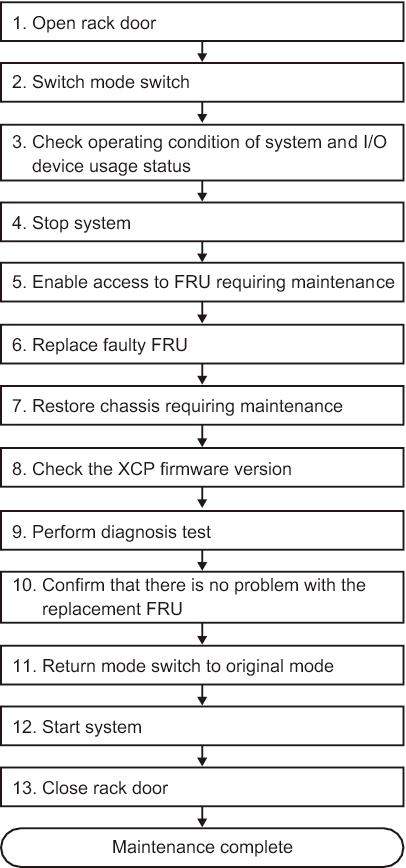
System-stopped/cold replacement (for a single-chassis configuration)
System-stopped/cold replacement can be performed on each FRU in a single-chassis configuration. Perform the following procedure to replace the unit.
|
Figure 7-12 System-stopped/cold replacement flow (for a single-chassis configuration)
|
|
| Item | Work procedure | Reference |
|---|---|---|
| 1 | Opening the rack door | |
| 2 | Switching the mode switch on the operation panel to Service mode | "5.2 Switching the Mode Switch to Service Mode" |
| 3 | Checking the operating condition of the system and the I/O device usage status | "5.3 Checking the Operating Condition and Resource Usage Status" |
| 4 | Stopping the system | "5.6 Stopping the Entire System" |
| 5 | Enabling access to the FRU requiring maintenance | "5.9 Accessing a FRU" |
| 6 | Replacing a faulty FRU | See the removal and installation procedures in the maintenance procedures for each FRU. "Chapter 8 Maintaining the PCI Express Cards" "Chapter 9 Maintaining the CPU Memory Unit/Memory" (*1)(*2) "Chapter 10 Maintaining the Internal Disks" "Chapter 11 Maintaining the Fan Units" "Chapter 12 Maintaining the Power Supply Units" "Chapter 13 Maintaining the PSU Backplane Unit/Operation Panel" (*1) "Chapter 15 Maintaining the Crossbar Units" |
| 7 | Restoring the chassis requiring maintenance | "6.1 Restoring the Chassis" |
| 8 | Checking the XCP firmware version (*3) | "9.11 Checking the XCP Firmware Version" |
| 9 | Performing a diagnosis test | "6.3.1 Diagnosing the system board" |
| 10 | Confirming that there is no problem with the replacement FRU | "6.3.3 Checking the FRU status after maintenance" |
| 11 | Returning the mode switch on the operation panel to Locked mode | "6.6 Returning the Mode Switch to Locked Mode" |
| 12 | Starting the system | "6.8 Starting the Entire System" |
| 13 | Closing the rack door | |
| *1 Simultaneous replacement of the CPU memory unit lower and PSU backplane unit is prohibited. To replace the CPU memory unit lower and PSU backplane unit, first replace either of the units and perform the work up to "10. Confirming that there is no problem with the replacement FRU." Then, return to "5. Enabling access to the FRU requiring maintenance," and replace the other unit. *2 If a CPU memory unit lower is replaced in the system of the hardware RAID volume in a hardware RAID configuration using internal disks, you need to reactivate the hardware RAID volume before performing the work in "12. Starting the system." For details, see "14.2.11 Re-enabling a Hardware RAID Volume" in the Fujitsu SPARC M12 and Fujitsu M10/SPARC M10 System Operation and Administration Guide. *3 In replacement of a FRU other than the CPU memory unit lower in "6. Replacing a faulty FRU," this work is not required. Even if you switched the microSD card when replacing the CPU memory unit lower, this work is not required. |
||
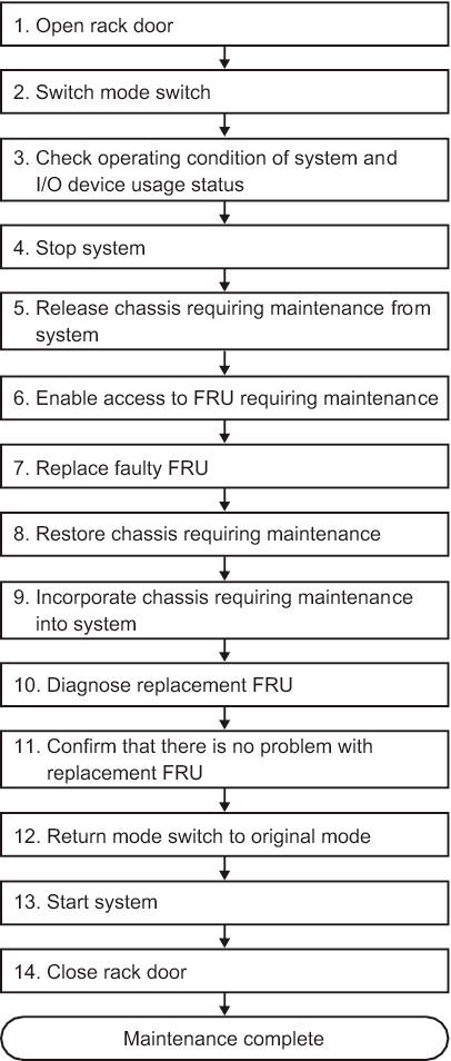
System-stopped/cold replacement (for a building block configuration)
System-stopped/cold replacement can be performed on each FRU in a building block configuration. Perform the following procedure to replace the unit.
|
Figure 7-13 System-stopped/cold replacement flow (for a building block configuration)
|
|
| Item | Work procedure | Reference |
|---|---|---|
| 1 | Opening the rack door | |
| 2 | Switching the mode switch on the operation panel to Service mode | "5.2 Switching the Mode Switch to Service Mode" |
| 3 | Checking the operating condition of the system and the I/O device usage status | "5.3 Checking the Operating Condition and Resource Usage Status" |
| 4 | Stopping the system | "5.6 Stopping the Entire System" |
| 5 | Releasing the chassis requiring maintenance from the system | "5.8.1 Releasing of the SPARC M10-4S chassis (possible only in a system with a building block configuration)" |
| 6 | Enabling access to the FRU requiring maintenance | "5.9 Accessing a FRU" |
| 7 | Replacing a faulty FRU | See the removal and installation procedures in the maintenance procedures for each FRU. "Chapter 8 Maintaining the PCI Express Cards" "Chapter 9 Maintaining the CPU Memory Unit/Memory" (*1)(*2) "Chapter 10 Maintaining the Internal Disks" "Chapter 11 Maintaining the Fan Units" "Chapter 12 Maintaining the Power Supply Units" "Chapter 13 Maintaining the PSU Backplane Unit/Operation Panel" (*1) "Chapter 14 Maintaining the Crossbar Cables" "Chapter 15 Maintaining the Crossbar Units" "Chapter 16 Maintaining the XSCF BB Control Cables" "Chapter 17 Maintaining the XSCF DUAL Control Cables" |
| 8 | Restoring the chassis requiring maintenance | "6.1 Restoring the Chassis" |
| 9 | Incorporating the chassis requiring maintenance into the system | "6.2.1 Incorporation of the SPARC M10-4S chassis (possible only in a system with a building block configuration)" |
| 10 | Diagnosing the replacement FRU | "6.3.1 Diagnosing the system board" "6.3.2 Diagnosing the crossbar unit and crossbar cables" |
| 11 | Confirming that there is no problem with the replacement FRU | "6.3.3 Checking the FRU status after maintenance" |
| 12 | Returning the mode switch on the operation panel to Locked mode | "6.6 Returning the Mode Switch to Locked Mode" |
| 13 | Starting the system | "6.8 Starting the Entire System" |
| 14 | Closing the rack door | |
| *1 Simultaneous replacement of the CPU memory unit lower and PSU backplane unit is prohibited. To replace the CPU memory unit lower and PSU backplane unit, first replace either of the units and perform the work up to "11. Confirming that there is no problem with the replacement FRU." Then, return to "6. Enabling access to the FRU requiring maintenance," and replace the other unit. *2 If a CPU memory unit lower is replaced in the system of the hardware RAID volume in a hardware RAID configuration using internal disks, you need to reactivate the hardware RAID volume before performing the work in "13. Starting the system." For details, see "14.2.11 Re-enabling a Hardware RAID Volume" in the Fujitsu SPARC M12 and Fujitsu M10/SPARC M10 System Operation and Administration Guide. |
||
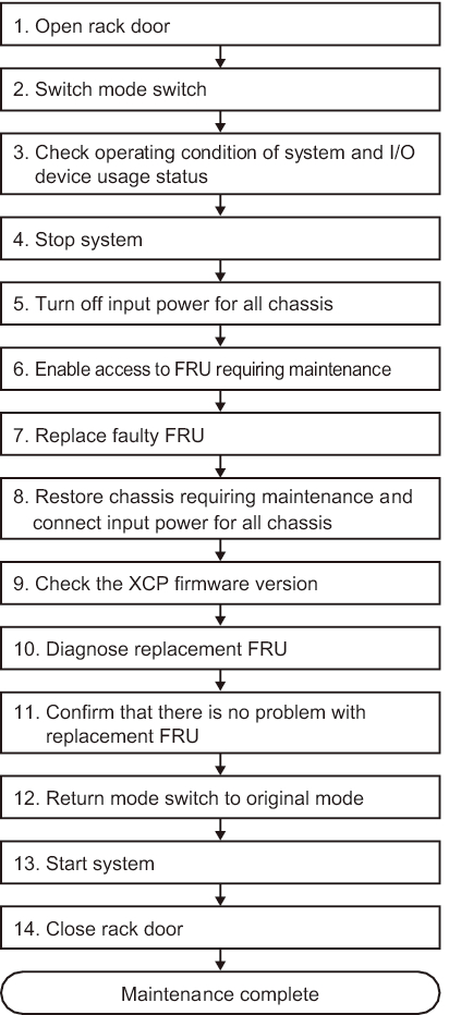
System-stopped/all power-off cold replacement (for a building block configuration)
System-stopped/all power-off cold replacement can be performed on each FRU in a building block configuration. Perform the following procedure to replace the unit.
|
Figure 7-14 System-stopped/all power-off cold replacement flow (for a building block configuration)
|
|
| Item | Work procedure | Reference |
|---|---|---|
| 1 | Opening the rack door | |
| 2 | Switching the mode switch on the operation panel to Service mode | "5.2 Switching the Mode Switch to Service Mode" |
| 3 | Checking the operating condition of the system and the I/O device usage status | "5.3 Checking the Operating Condition and Resource Usage Status" |
| 4 | Stopping the system | "5.6 Stopping the Entire System" |
| 5 | Turning off the input power for all chassis | "5.9.4 Removing the power cord" |
| 6 | Enabling access to the FRU requiring maintenance | "5.9 Accessing a FRU" |
| 7 | Replacing a faulty FRU | See the removal and installation procedures in the maintenance procedures for each FRU. "Chapter 8 Maintaining the PCI Express Cards" "Chapter 9 Maintaining the CPU Memory Unit/Memory" (*1)(*2) "Chapter 10 Maintaining the Internal Disks" "Chapter 11 Maintaining the Fan Units" "Chapter 12 Maintaining the Power Supply Units" "Chapter 13 Maintaining the PSU Backplane Unit/Operation Panel" (*1) "Chapter 14 Maintaining the Crossbar Cables" "Chapter 15 Maintaining the Crossbar Units" "Chapter 16 Maintaining the XSCF BB Control Cables" "Chapter 17 Maintaining the XSCF DUAL Control Cables" |
| 8 | Restoring the chassis requiring maintenance and connecting the input power for all chassis (*3)(*4)(*5) | "6.1 Restoring the Chassis" |
| 9 | Checking the XCP firmware version (*6) | "9.12 Checking the XCP Firmware Version (Building Block Configuration)" |
| 10 | Diagnosing the replacement FRU | "6.3.1 Diagnosing the system board" "6.3.2 Diagnosing the crossbar unit and crossbar cables" |
| 11 | Confirming that there is no problem with the replacement FRU | "6.3.3 Checking the FRU status after maintenance" |
| 12 | Returning the mode switch on the operation panel to Locked mode | "6.6 Returning the Mode Switch to Locked Mode" |
| 13 | Starting the system | "6.8 Starting the Entire System" |
| 14 | Closing the rack door | |
| *1 Simultaneous replacement of the CPU memory unit and PSU backplane unit is prohibited. To replace the CPU memory unit and PSU backplane unit, first replace either of the units and perform the work up to "11. Confirming that there is no problem with the replacement FRU." Then, return to "6. Enabling access to the FRU requiring maintenance," and replace the other unit. *2 If a CPU memory unit lower is replaced in the system of the hardware RAID volume in a hardware RAID configuration using internal disks, you need to reactivate the hardware RAID volume before performing the work in "13. Starting the system." For details, see "14.2.11 Re-enabling a Hardware RAID Volume" in the Fujitsu SPARC M12 and Fujitsu M10/SPARC M10 System Operation and Administration Guide. *3 If you have replaced the CPU memory unit lower and the XCP firmware version is different between the maintenance part and the existing system, the message "XSCF firmware update now in progress. BB#xx, please wait for XSCF firmware update complete." appears at login to the XSCF. Then, the XCP firmware version will be automatically matched. The version matching takes about 50 minutes. Execute the showlogs monitor command, and check for the "XCP firmware version synchronization completed" message. The displayed message indicates the completion of XCP firmware matching. *4 If you have replaced the CPU memory unit lower using the replacement microSD card in "7. Replacing a faulty FRU," the "SCF:Gaps between BB-ID" message may appear in the error log. If so, ignore the message. *5 If you have replaced the CPU memory unit lower in "7. Replacing a faulty FRU," the "SCF:SCF Diagnosis initialize RTC" message may appear in the error log. If so, ignore the message. *6 In replacement of a FRU other than the CPU memory unit lower in "7. Replacing a faulty FRU," this work is not required. Even if you switched the microSD card when replacing the CPU memory unit lower, this work is not required. |
||
< Previous Page | Next Page >