2.11 Checking the Functions of the Operation Panel
2.11 Checking the Functions of the Operation Panel
This section describes the functions of the operation panels mounted on the SPARC M10-4S and the crossbar box.
You can check system operation with the system display (LEDs) and operation functions on the operation panels.
You can check system operation with the system display (LEDs) and operation functions on the operation panels.
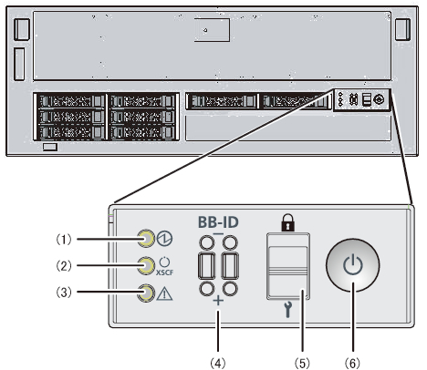
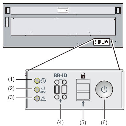
Figure 2-29 shows the SPARC M10-4S operation panel, Figure 2-31 shows the crossbar box operation panel, and Table 2-18 shows the LEDs and switches on the operation panels.
For details on system operations not covered in the functional outline of Table 2-18, see "2.3 Confirming the Functions of the Operation Panel" in the Fujitsu M10-4/Fujitsu M10-4S/SPARC M10-4/SPARC M10-4S Service Manual.
| Note - In the building block configuration, the mode switch function and the POWER switch function are invalid on an operation panel other than the master XSCF. |
| Note - In the building block configuration with the crossbar box connected, all the functions of the operation panel becomes valid only on the operation panel of a crossbar box that is the master XSCF. |
|
Figure 2-30 SPARC M10-4S operation panel
|
|
|
Figure 2-31 Crossbar box operation panel
|
|
| No. | LED/Switch | Functional outline |
|---|---|---|
| 1 | POWER LED | Indicates the operating status of the system. On: The system is running. Off: The system is stopped. Blinking: The system is in the stop processing. |
| 2 | XSCF STANDBY LED | Indicates the XSCF status of the system. On: The XSCF is running. Off: The XSCF is stopped. Blinking: The XSCF is starting. |
| 3 | CHECK LED | Indicates whether the SPARC M10-4S is in an abnormal state. Off: Normal, or no power being supplied On: Hardware has detected an error. |
| 4 | BB-ID switch | Sets the ID identifying a chassis. |
| 5 | Mode switch | Sets the system operation mode. |
| 6 | POWER switch | Starts/Stops the system. |
You can perform the following operations with the switches shown at (4) to (6) in Figure 2-30 and Figure 2-31.
- BB-ID switch
This switch sets the ID number of the SPARC M10-4S/crossbar box in the building block configuration. Table 2-18 shows how to operate the BB-ID switch. For the setting of the BB-ID number, see "4.1 Setting the ID (BB-ID) Identifying a Chassis." - Mode switch
This switch sets the start mode for the system. You can switch between Locked mode and Service mode on the mode switch by sliding the switch.
- Locked mode ( )
)
This switch sets the start mode for the system.
You can switch from Service mode to Locked mode on the mode switch by sliding the switch.
- Service mode ( )
)
This mode is used during maintenance work.
You can turn off the power with the POWER switch, but the switch is inhibited from turning on the power. Maintenance with the whole system stopped is performed in Service mode. - POWER switch
You can start or stop the system.
In the building block configuration, the POWER switch is available for operation only on the SPARC M10-4S/crossbar box of the master XSCF. Set the same operation mode for the master XSCF and the standby XSCF.
< Previous Page | Next Page >