B.1 2BB Configuration (Direct Connections between Chassis)
B.1 2BB Configuration (Direct Connections between Chassis)
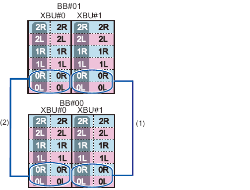
The numbers enclosed in parentheses in Figure B-1 indicate the connection order. For details, see Table B-1.
|
Figure B-1 Crossbar cable (electrical) connection diagram
|
|
| Connection order | Connector 1 | Connector 2 | Remarks |
|---|---|---|---|
| 1 | BB00-XBU1-0L (pink) | BB01-XBU1-0L (pink) | BB#00 - BB#01 |
| BB00-XBU1-0L (black) | BB01-XBU1-0L (black) | ||
| BB00-XBU1-0R (light blue) | BB01-XBU1-0R (light blue) | ||
| BB00-XBU1-0R (black) | BB01-XBU1-0R (black) | ||
| 2 | BB00-XBU0-0L (pink) | BB01-XBU0-0L (pink) | |
| BB00-XBU0-0L (black) | BB01-XBU0-0L (black) | ||
| BB00-XBU0-0R (light blue) | BB01-XBU0-0R (light blue) | ||
| BB00-XBU0-0R (black) | BB01-XBU0-0R (black) |
|
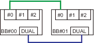
Figure B-2 XSCF cable connection diagram
|
|
| Connected chassis | Connector 1 | Connector 2 |
|---|---|---|
| BB#00 - BB#01 | BB00-DUAL | BB01-DUAL |
| BB00-XSCF0 | BB01-XSCF0 |
< Previous Page | Next Page >