6.2.2 Turning on the input power and starting the XSCF
6.2.2 Turning on the input power and starting the XSCF
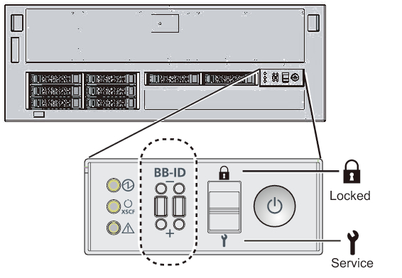
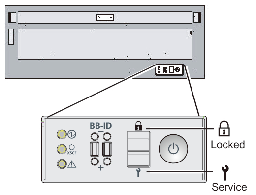
- Set the mode switch on the operation panel to the Service position. For a building block configuration, set the mode switches on the master chassis and the chassis that has the standby XSCF to the Service position.
The Service position is indicated by a wrench icon. The Locked position is indicated by a lock icon.
| Note - Set the master chassis and the chassis that has the standby XSCF to the same mode. If their settings are different, an asterisk (*) is shown beside the components in the output of the showhardconf or showstatus command. |
| Remarks - In a building block configuration with direct connections between chassis, change the mode switches of BB-ID#00 and #01 to Service mode. In a building block configuration with connections through crossbar boxes, change the mode switches of BB-ID#80 and #81 to Service mode. |
|
Figure 6-1 Mode switch on the operation panel of the SPARC M10-4S
|
|
|
Figure 6-2 Mode switch on the operation panel of a crossbar box
|
|
- Confirm that the power cord connector is connected to a power supply unit of the chassis.
- Connect the power cord plug to an outlet.a. If the outlet has a circuit breaker, turn on the circuit breaker switch.b. When using an expansion rack, open the rear door of the rack and push in all the CB switches on the PDU.
When pushed in, a CB switch is turned on. When pulled up, the switch is turned off.
Figure 3-3 shows the location of the PDU for single-phase power feed and the location of the CB switch on the PDU for three-phase power feed. Two units of either type of PDU are mounted for each expansion rack.
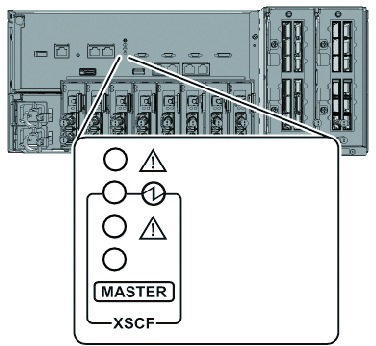
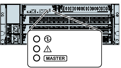
A in Figure 3-3 is the CB switch. A PDU has 12 CB switches, so there are 24 switches per rack. - Check the XSCF unit LEDs.a. The CHECK LED of the XSCF unit goes on for an instant immediately after the input power is turned on.b. The READY LED of the XSCF unit flashes during XSCF initialization and stays on after the initialization completes.c. For a building block configuration, the MASTER LED of only the XSCF unit of the master XSCF goes on.
| Note - In a building block configuration with direct connections between chassis, BB#00 is the chassis of the master XSCF. In a building block configuration with connections through crossbar boxes, BB#80 is the chassis of the master XSCF. If the MASTER LED of BB#00 or BB#80 does not go on, the master chassis may have been switched. Check the MASTER LED of the XSCF of BB#01 or BB#81. If it has been switched, connect the system management terminal to the chassis whose MASTER LED is on. |
|
Figure 6-3 Rear of the SPARC M10-4S
|
|
|
Figure 6-4 Rear view of a crossbar box
|
|
< Previous Page | Next Page >