5.1 Connecting Cables to the SPARC M10-4S
5.1 Connecting Cables to the SPARC M10-4S
This section describes the procedure for connecting the serial cable, network cables, and power cords to the SPARC M10-4S.
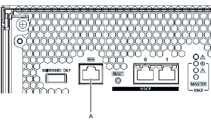
- Connect the serial cable supplied with the chassis from the serial port of the XSCF unit (A in Figure 5-1) to the system management terminal.
In a building block configuration, the system operates with batch operations by the chassis of the master XSCF. Connect the serial cable to the master XSCF.
| Note - In a building block configuration with direct connections between chassis, BB#00 is usually the master XSCF, and BB#01 is the standby XSCF. If the master is switched, BB#01 becomes the master XSCF, and BB#00 becomes the standby XSCF. |
| Note - In a building block configuration with connections through crossbar boxes, the system operates with batch operations by the master XSCF of the crossbar box. No serial cable is connected to the SPARC M10-4S. |
|
Figure 5-1 Serial port location
|
|
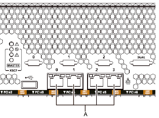
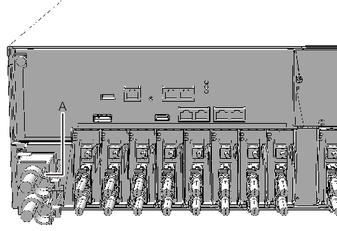
- Connect a LAN cable of Category 5 or higher from a GbE port (A in Figure 5-2) to the network switch or hub.
The GbE ports are used for the user network. Connect the other servers, other PCs, UPS, etc. that are necessary for business via the network switch or hub.
|
Figure 5-2 GbE port locations
|
|
- If a PCIe card is mounted, connect a LAN cable and I/O cable to the respective ports on the PCIe card.
- Secure the cables to the cable support.
While leaving extra length, secure the cables connected to the PCIe card to the cable support. - Connect the supplied power cords to the power supply units.
The work in this step differs depending on the rack where the SPARC M10-4S is mounted.
Perform the work appropriate to the rack type.
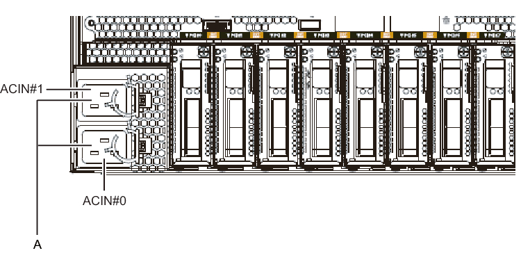
- Mounting in a general racka. Connect the supplied power cords to the power supply units (A in Figure 5-5). Insert the power cords straight into the power supply units all the way.
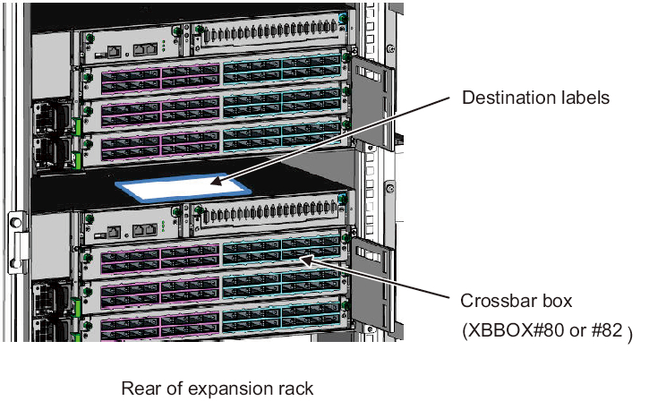
- Mounting in an expansion racka. Affix destination labels to the power cords.
Labels are affixed on the top panel of the crossbar box XBBOX#80 or XBBOX#82 at the rear of the expansion rack. (See Figure 5-4.)
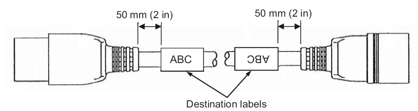
Affix labels with the same indications to both ends of each power cord.
First affix the text part of a label to the power cord, and then wrap the label around the cord.
For the label orientation and locations for affixing the labels, see Figure 5-3.
For lists for affixing labels, see "B.6 Power Cord Connections in Expansion Racks."
|
Figure 5-3 Locations for affixing labels (for an expansion rack)
|
|
|
Figure 5-4 Destination label storage location: Top panel of the lower crossbar box
|
|
- b. Connect the power cords to the power supply units (A in Figure 5-5) according to the destination labels.
Insert the power cords straight into the power supply units all the way.
|
Figure 5-5 Power supply unit locations
|
|
| Note - Do not connect to an outlet at this point. |
|
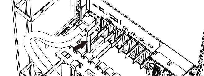
Figure 5-6 Inserting power cords
|
|
- Secure all the power cords with cable clamps.
Clip on the power cords to the cable clamps, and secure the cable clamps.
After locking each clasp (A in Figure 5-7), push the cable clamp toward the front of the chassis to firmly secure the clamp.
|
Figure 5-7 Locking a cable clamp
|
|
< Previous Page | Next Page >