2.10 Checking External Interface Port Specifications
2.10 Checking External Interface Port Specifications
This section provides an overview of the specifications of the external interface ports required in installation and operation of the SPARC M10-4S.
You can use the following external interface ports on the SPARC M10-4S.
You can use the following external interface ports on the SPARC M10-4S.
XSCF unit administration port
- Serial port
The eXtended System Control Facility (XSCF) has one RS-232C-compliant serial port. You can monitor and control the system by connecting the system management terminal to the serial port. Functions that require TCP/IP are not available through the serial port. - XSCF-LAN port
In addition to the serial port, the XSCF has two 1000BASE-T LAN ports. You can remotely monitor and control the system by configuring a system control network using a LAN port. There are two types of interfaces available: a command-line interface (XSCF shell) and a browser user interface (XSCF Web).
The XSCF-LAN ports support auto-negotiation only. Therefore, the communication speed/mode for the XSCF-LAN ports cannot be configured.
Do not make a connection with a network switch or hub until you complete the network setting for the XSCF. If a connection is made before the completion of the setting, devices connected with others may become unable to communicate, or unauthorized login by a malicious third party to the XSCF of this chassis may not be preventable. - XSCF USB port (for field engineers)
Field engineers use this port to download information from the XSCF. - XSCF DUAL control port
Use this port to connect the master XSCF and the standby XSCF.
The port implements the SP to SP communication protocol (SSCP) for the SPARC M10-4S. - XSCF BB control port
The port is used to connect the master XSCF and standby XSCF to each slave XSCF. There are three ports.
The port implements the SP to SP communication protocol (SSCP) for the SPARC M10-4S.
Other unit ports
- GbE LAN port
The port is used to connect Oracle Solaris to the network. There are four ports.
Connection to the network is also possible through a LAN card, which is provided by the customer, mounted in a PCI Express (PCle) slot. - SAS port
This port is used to connect an external SAS device. - USB port
This is a general-purpose USB port. Use the port to connect an external USB DVD device, etc.
LAN port LEDs
- LINK SPEED LED
This LED indicates the communication speed of the XSCF-LAN port and GbE LAN port (Figure 2-27). - ACT LED (green)
This LED indicates the communication state of the XSCF-LAN port and GbE LAN port (Figure 2-27).
|
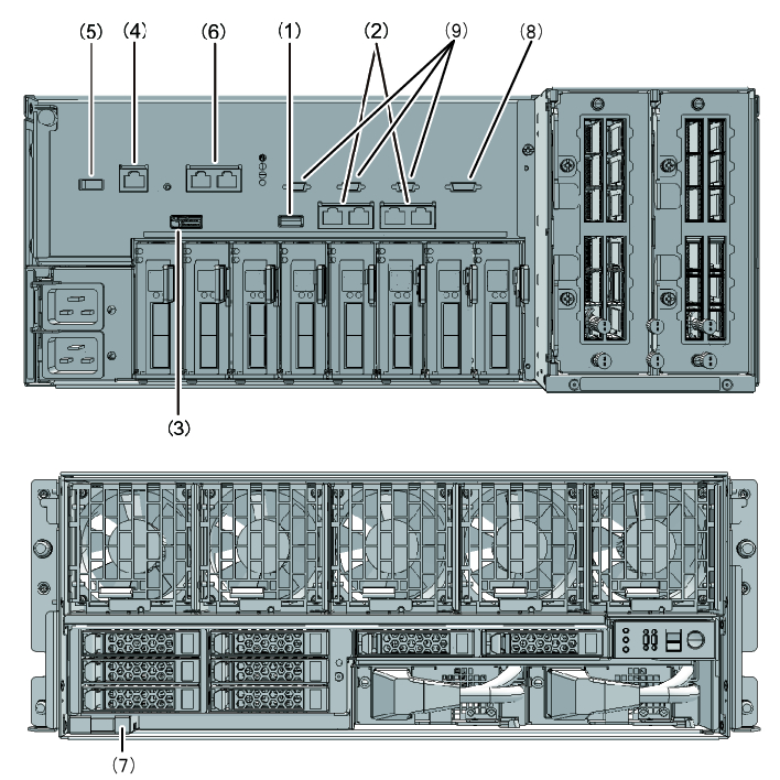
Figure 2-25 Locations of the ports for network connections (SPARC M10-4S)
|
|
| No. | Port | Number on board |
|---|---|---|
| 1, 7 | USB port | 2 |
| 2 | GbE LAN port | 4 |
| 3 | SAS port | 1 |
| 4 | Serial port | 1 |
| 5 | XSCF USB port (for field engineers) | 1 |
| 6 | XSCF-LAN port | 2 |
| 8 | XSCF DUAL control port | 1 |
| 9 | XSCF BB control port | 3 |
|
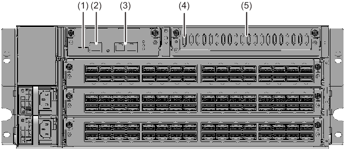
Figure 2-26 Locations of the ports for network connections (crossbar box)
|
|
| No. | Port | Number on board |
|---|---|---|
| 1 | XSCF USB port (for field engineers) | 1 |
| 2 | Serial port | 1 |
| 3 | XSCF-LAN port | 2 |
| 4 | XSCF DUAL control port | 1 |
| 5 | XSCF BB control port | 19 |
|
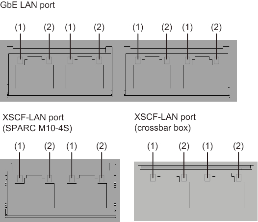
Figure 2-27 LAN port LEDs
|
|
| No. | Name | Color | State | Port |
|---|---|---|---|---|
| 1 | LINK SPEED | Amber | On | The communication speed is 1 Gbps. |
| Green | On | The communication speed is 100 Mbps. | ||
| - | Off | The communication speed is 10 Mbps. | ||
| 2 | ACT | Green | Blinking | The port is sending/receiving data. |
| - | Off | The port is not sending/receiving data. |
< Previous Page | Next Page >