5.3 Connecting Cables to a Crossbar Box
5.3 Connecting Cables to a Crossbar Box
This section describes the procedure for connecting the serial cable to a crossbar box.
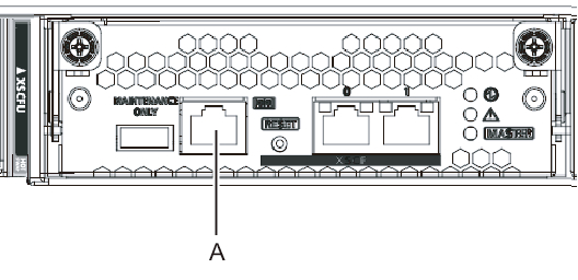
- Connect the serial cable supplied with the chassis from the serial port of the XSCF unit (A in Figure 5-15) to the system management terminal.
In a building block configuration, the system operates with batch operations by the chassis of the master XSCF. Connect the serial cable to the master XSCF.
| Note - In a building block configuration with connections through crossbar boxes, XBBOX#80 is usually the master XSCF, and XBBOX#81 is the standby XSCF. If the master is switched, XBBOX#81 becomes the master XSCF, and XBBOX#80 becomes the standby XSCF. |
| Note - In a building block configuration with connections through crossbar boxes, no serial cable is connected to the SPARC M10-4S. |
|
Figure 5-15 Serial port location
|
|
- Confirm that the SPARC M10-4S and crossbar box power cords are connected to the PDUs of the expansion rack.
The SPARC M10-4S and crossbar box power cords are shipped connected to the PDUs of the expansion rack.
If the SPARC M10-4S has been mounted on site, connect the power cords to the PDUs at this time. - Confirm that the CB switches of the PDUs of the expansion rack are OFF.
< Previous Page | Next Page >