9.2.2 Adding the server after stopping the target physical partition (PPAR)
9.2.2 Adding the server after stopping the target physical partition (PPAR)
This section describes the SPARC M10-4S addition procedure for expanding from the 2BB configuration to the 3BB configuration after stopping the target physical partition (PPAR).
Stop applications in guest domains as required.
For details on the XSCF commands executed in each step, see the Fujitsu SPARC M12 and Fujitsu M10/SPARC M10 XSCF Reference Manual.
Stop applications in guest domains as required.
For details on the XSCF commands executed in each step, see the Fujitsu SPARC M12 and Fujitsu M10/SPARC M10 XSCF Reference Manual.
- Log in to the master XSCF.
Execute the showbbstatus command to confirm that the XSCF to which you have logged in is the master XSCF.
If it is a standby XSCF, retry to log in to the master XSCF.
| XSCF> showbbstatus BB#00 (Master) |
- Execute the showsscp command to check whether the IP address of the SP to SP communication protocol (SSCP) is a default value or a value set by a user.
| XSCF> showsscp |
| Note - For the default values of SSCP IP addresses, see "3.9.5 Understanding the IP Addresses that are Set with SSCP" in the Fujitsu SPARC M12 and Fujitsu M10/SPARC M10 System Operation and Administration Guide. |
- If the IP address is a default value and the default value should also be used for the IP address of the SPARC M10-4S to be added, go to the next step.
To set a user value, use the setsscp command to set an IP address, use the applynetwork command to apply the SSCP IP address of the target SPARC M10-4S, and confirm that it was reflected. Then, execute the rebootxscf command to complete settings, and go to the next step. For details on the procedure, see "7.5.6 Applying network settings."
- Check the number of CPU Activations registered in the entire system.
If the number of CPU Activations registered in the system becomes short compared to the number of added CPU cores, purchase a CPU Activation key and execute the addcodactivation command to add the key to the system.
The following example displays the CPU Activations in the system that are already fully used.
| XSCF> showcodusage -p resource Resource In Use Installed CoD Permitted Status -------- ------ --------- ------------- ------ PROC 64 64 64 OK |
- For details on adding a CPU Activation key, see "7.11.3 Registering a CPU Activation key."
- Execute the poweroff command to stop the physical partition that is the incorporation destination of the added SPARC M10-4S.
Specify the physical partition number of the incorporation destination in ppar_id.
| XSCF> poweroff -y -p ppar_id |
- The following example stops PPAR#0.
| XSCF> poweroff -y -p 0 PPAR-IDs to power off:00 Continue? [y|n]:y 00:Powering off *Note* This command only issues the instruction to power-off. The result of the instruction can be checked by the "showpparprogress". |
- Add the SPARC M10-4S.a. Execute the addfru command, and add the SPARC M10-4S by following the messages.
| Note - If no SSCP IP address is set, an error occurs. |
| Note - The addfru command cannot specify multiple chassis. Add one chassis at a time. |
| Note - When the addfru command is executed, the firmware of the building block to be added is automatically matched to the version of the firmware of the building block in which the master XSCF is operating. It is recommended that you update the XCP of the master XSCF to the latest version beforehand. |
The following example adds BB#2.
| XSCF> addfru ----------------------------------------------------------------------- Maintenance/Addition Menu Please select the chassis including added FRU. No. FRU Status --- ------------------- -------------- 1 /BB#0 Normal 2 /BB#1 Normal 3 /BB#2 Unmount 4 /BB#3 Unmount ----------------------------------------------------------------------- Select [1-16|c:cancel] :3 Maintenance/Addition Menu Please select the BB or a type of FRU to be added. 1. BB itself 2. PSU (Power Supply Unit) ----------------------------------------------------------------------- Select [1,2|c:cancel] :1 Maintenance/Addition Menu Please select a FRU to be added. No. FRU Status --- ------------------- -------------- 1 /BB#2 Unmount ----------------------------------------------------------------------- Select [1|b:back] :1 You are about to add BB#2. Do you want to continue?[a:add|c:cancel] :a Please execute the following steps: 1) After the added device is connected with the system, please turn on the breaker of the BB#2. 2) Please select[f:finish] : |
- b. Mount the target SPARC M10-4S in the rack.Mount the target SPARC M10-4S in the rack when the above message, "1) After the added device is connected with the system, please turn on the breaker of the BB#2.", appears during command execution.For the mounting procedure, see "3.4.1 Mounting the SPARC M10-4S in a rack."
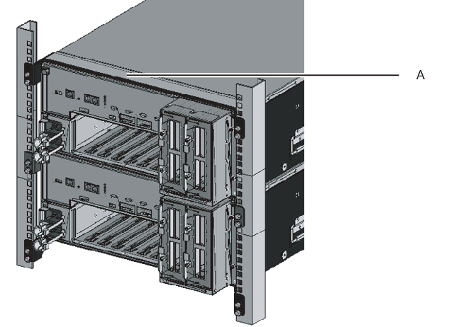
| Remarks - When adding the SPARC M10-4S in an existing expansion rack, you need to remove the protection bracket and blank panel of the mounting space (A in Figure 9-2). The blank panel is secured with two M6 screws. The protection bracket is secured with four M6 screws. Store the removed blank panel and M6 screws for future use when the SPARC M10-4S is removed. Install the protection bracket and M6 screws at their original locations, for future use when the expansion rack is moved. |
|
Figure 9-2 Protection bracket
|
|
- c. Set the ID of the target SPARC M10-4S.For details, see "4.1 Setting the ID (BB-ID) Identifying a Chassis."
- d. Connect the additional crossbar cables.For a cable routing diagram of connections and a cable list, see "Appendix B Cable Connection Information on Building Block Configurations."For details on the connections in direct connections between chassis, see "4.2 Connecting Cables (for Direct Connections between Chassis)."
| Remarks - For connections through crossbar boxes, the additional crossbar cables (optical) are secured to the expansion rack. When packed, the cables are tied to a rack column with their connectors wrapped in a bag. Remove the cable connectors from the rack column and unpack them. For details, see Figure 4-13. |
- e. Connect the additional XSCF BB control cables.For a cable routing diagram of connections and a cable list, see "Appendix B Cable Connection Information on Building Block Configurations."For details on the connections in direct connections between chassis, see "4.2 Connecting Cables (for Direct Connections between Chassis)."
- f. If the addition expands the 1BB configuration to a multiple BB configuration, connect the XSCF DUAL control cable from the XSCF DUAL control port of BB#00 to the XSCF DUAL control port of BB#01.Since you are expanding the 2BB configuration to the 3BB configuration, this step is not necessary.
- g. Connect LAN cables to the target SPARC M10-4S.For details, see "5.1 Connecting Cables to the SPARC M10-4S."
- h. Connect the power cords of the target SPARC M10-4S to the input power supply.
- i. Enter [f] from the command execution screen of the master XSCF.
| 2) Please select[f:finish] :f Waiting for BB#2 to enter install state. [This operation may take up to 20 minute(s)] (progress scale reported in seconds) 0..... 30.... done Waiting for BB#2 to enter ready state. [This operation may take up to 45 minute(s)] (progress scale reported in seconds) 0..... 30..... 60... done Do you want to start to diagnose BB#2?[s:start|c:cancel] : |
- j. Skip the diagnosis of the building block to be added, and then end the addfru command.Enter [c] from the input screen of the addfru command of the master XSCF to skip the diagnosis processing for the BB to be added.When "The addition of BB#2 has completed." is output, enter [f] and then [c] at the end to end the addfru command.
| Do you want to start to diagnose BB#2?[s:start|c:cancel] :c Diagnostic tests are about to be skipped. Running diagnostic tests are strongly recommended before using BB#2. Are you sure you want to skip testing?[y:yes|n:no] :y ------------------------------------------------------------------------------ Maintenance/Addition Menu Status of the added FRU. FRU Status ------------------- -------------- /BB#2 Normal ------------------------------------------------------------------------------ [Warning:007] Running diagnostic tests on BB#2 is strongly recommended after addfru has completed. The addition of BB#2 has completed.[f:finish] :f ------------------------------------------------------------------------------ Maintenance/Addition Menu Please select the chassis including added FRU. No. FRU Status --- ------------------- -------------- 1 /BB#0 Normal 2 /BB#1 Normal 3 /BB#2 Normal 4 /BB#3 Unmount ------------------------------------------------------------------------------ Select [1,2|c:cancel] :c |
- Diagnose the added SPARC M10-4S.a. Execute the testsb command to perform a diagnosis test on the added SPARC M10-4S.Specify the PSB number of the diagnosis target PSB in XX-Y. XX is a BB-ID, and Y is fixed at 0.An initial diagnosis and connection I/O check are performed on the diagnosis target PSB.<Description of options specified>-v: Additionally displays detailed messages of the initial diagnosis-p: Executes the "probe-scsi-all" command of OpenBoot PROM and displays the results while a diagnosis is being processed-s: Executes the "show-devs" command of OpenBoot PROM and displays the results while a diagnosis is being processed-y: Automatically responds with "y" to a query
| XSCF> testsb -v -p -s -y XX-Y |
- The following example performs a diagnosis test on the added BB#02.
| XSCF> testsb -v -p -s -y 02-0 Initial diagnosis is about to start, Continue?[y|n] :y PSB#02-0 power on sequence started. |
- If an error is displayed, see "A.2.4 Checking diagnosis results."
- Perform a diagnosis test on the crossbar cables.
- a. Execute the showboards command to check the PSB number (BB-ID) assigned to the physical partition stopped in step 3 and the PSB number (BB-ID) of the added PSB.
| XSCF> showboards -a PSB PPAR-ID(LSB) Assignment Pwr Conn Conf Test Fault ---- ------------ ----------- ---- ---- ---- ------- -------- 00-0 00(00)(*1) Assigned n n n Passed Normal 01-0 00(01)(*1) Assigned n n n Passed Normal 02-0 SP (*2) Unavailable n n n Passed Normal |
- b. Execute the diagxbu command to check the cables.
Specify the BB-ID of the added BB in XX. (*2) indicates this BB-ID checked in step b.
In YY, specify the BB-ID of the BB incorporated into the physical partition. (*1) indicates this BB-ID checked in step b.
| XSCF> diagxbu -y -b XX -t YY [-t zz] |
- The following example performs a diagnosis between the added BB#02 and the incorporated BB#00 and BB#01 in PPAR#0.
| XSCF> diagxbu -y -b 02 -t 00 -t 01 XBU diagnosis is about to start, Continue?[y|n] :y Power on sequence started. [7200sec] 0..... 30..... 60..... 90..end XBU diagnosis started. [7200sec] 0..... 30..... 60..... 90.....120.....150.....180.....210.....240.....| 270.....300.....330.....360.....390.....420.....450.....480.....510.....\ 540.....570.....600.....630.....660.....690.....720.....750.....780.....| 810.....840.....870.....900.....930.....960.....990.....1020.....1050.....\ 1080.....1110...end completed. Power off sequence started. [1200sec] 0..... 30..... 60..... 90.....120.....150.....180.....210...end completed. |
- c. Execute the showlogs error command, and confirm that no error is displayed.
| XSCF> showlogs error |
- If an error is displayed, see "A.2.2 Checking the contents of logs."
- d. Execute the showhardconf command to check the configuration, status, and quantities.For details, see "6.8 Checking the Component Status."
- If the addition expanded the 1BB configuration to a multiple-BB configuration, configure the XSCF network.
For details, see "7.5.2 Setting an Ethernet (XSCF-LAN) IP address" and "7.5.3 Setting a takeover IP address."
After configuration, execute the applynetwork command to apply the settings, and confirm that they were reflected. Then, execute the rebootxscf command to complete settings, and go to the next step. For details on the procedure, see "7.5.6 Applying network settings."
Since you are expanding the 2BB configuration to the 3BB configuration, this work is not necessary. - To configure memory mirroring for the added SPARC M10-4S, set memory mirror mode.
For details, see "7.6 Configuring Memory Mirroring."
If you do not use memory mirror mode, this work is not necessary.
- Register the system board of the added SPARC M10-4S in the physical partition configuration list.a. Execute the showpcl command to check the physical partition configuration list.
| XSCF> showpcl -p 0 PPAR-ID LSB PSB Status 00 Powered off 00 00-0 01 01-0 |
- b. Execute the setpcl command to register the system board with the physical partition.The following example associates system board 02-0 with logical system board 02 of physical partition 0.
| XSCF> setpcl -p 0 -a 02=02-0 |
- c. Execute the showpcl command, and confirm the configured physical partition.
| XSCF> showpcl -p 0 PPAR-ID LSB PSB Status 00 Powered off 00 00-0 01 01-0 02 02-0 |
- Set the number of CPU Activations in the physical partition, and add CPU core resources.a. Execute the showcodusage command to display the CPU Activation information.The following example displays the CPU Activation information.
The system here has 192 CPU core resources installed and 192 CPU Activations registered. The example shows that the CPU core resources are not in use and that the 192 CPU Activations are currently not in use.
| XSCF> showcodusage -p resource Resource In Use Installed CoD Permitted Status -------- ------ --------- ------------- ------ PROC 0 192 192 OK: 192 cores available Note: Please confirm the value of the "In Use" by the ldm command of Oracle VM Server for SPARC. The XSCF may take up to 20 minutes to reflect the "In Use" of logical domains. |
- b. Execute the showcod command to check the CPU Activation information set for the physical partition.
| XSCF> showcod -p 0 PROC Permits assigned for PPAR 0: 64 |
- c. If the assigned resources are insufficient, execute the setcod command to assign CPU resources to the physical partition.The following example adds 64 CPU core resources to physical partition 0.
| XSCF> setcod -p 0 -s cpu -c add 64 PROC Permits assigned for PPAR 0 : 128 -> 192 PROC Permits assigned for PPAR will be changed. Continue? [y|n] :y Completed. |
| Note - The -c add, -c delete, and -c set options are not supported if the XSCF firmware is XCP 2250 or earlier. Specify the option of the setcod command as shown below to add or delete interactively. |
| XSCF> setcod -s cpu |
- d. Execute the showcod command again to check the CPU Activation information set for the physical partition.
| XSCF> showcod -p 0 PROC Permits assigned for PPAR 0: 192 |
- Incorporate the system board of the added SPARC M10-4S into the physical partition.
| Note - Suppose you add the added SPARC M10-4S together with a PCI expansion unit connected to it and enable/disable the direct I/O function of the PCI expansion unit. In this case, execute the setpciboxdio command to enable/disable it before executing the addboard command for incorporation in the physical partition. When you have changed the setting of the direct I/O function, do not restart the logical domains until you execute the ldm add-spconfig command to save the logical domain configuration in XSCF. |
| Note - Pull out all the PCIe cassettes with the PCIe card for the PCI expansion unit to be installed. After incorporating the link card into the server, attach the pulled-out PCIe cassette to the PCI expansion unit. Then, install the PCIe card of the PCI expansion unit on the server by using PHP. |
- a. Return to the XSCF shell, execute the showboards command, and check the system board (PSB) status.In the following example, system board 02-0 is in the system board pool.
| XSCF> showboards -p 0 PSB PPAR-ID(LSB) Assignment Pwr Conn Conf Test Fault ---- ------------ ----------- ---- ---- ---- ------- -------- 00-0 00(00) Assigned n n n Passed Normal 01-0 00(01) Assigned n n n Passed Normal 02-0 SP Available n n n Passed Normal |
- b. Execute the addboard command to assign the system board (PSB).The following example assigns system board 02-0 to physical partition 0.
| XSCF> addboard -c assign -p 0 02-0 PSB#02-0 will be assigned into PPAR-ID 0. Continue?[y|n] :y |
- c. Execute the showresult command to confirm the end status of the previously executed addboard command.In the following example, 0 is returned as the end status, so the execution of the addboard command has completed correctly.
| XSCF> showresult 0 |
- d. Execute the showboards command to check the system board (PSB) status, and confirm that the system board (PSB) has been added.
| XSCF> showboards -p 0 PSB PPAR-ID(LSB) Assignment Pwr Conn Conf Test Fault ---- ------------ ----------- ---- ---- ---- ------- -------- 00-0 00(00) Assigned n n n Passed Normal 01-0 00(01) Assigned n n n Passed Normal 02-0 00(02) Assigned n n n Passed Normal |
- Start the physical partition.
The following example starts PPAR#0.
| XSCF> poweron -y -p 0 |
- Execute the showpparstatus command to check the operation status of the physical partition.
In the following example, the [PPAR Status] field displays "Running," so the physical partition is operating correctly.
| XSCF> showpparstatus -p 0 PPAR-ID PPAR Status 00 Running |
- Execute the showboards command to check the system board (PSB) status.
In the following example, since both the [Conn] and [Conf] fields display "y" for system board 02-0, the system board (PSB) has been added correctly.
| XSCF> showboards -p 0 PSB PPAR-ID(LSB) Assignment Pwr Conn Conf Test Fault ---- ------------ ----------- ---- ---- ---- ------- -------- 00-0 00(00) Assigned y y y Passed Normal 01-0 00(01) Assigned y y y Passed Normal 02-0 00(02) Assigned y y y Passed Normal |
- Reconfigure the logical domains.
Assign the resources of the added SPARC M10-4S to an existing logical domain or a newly configured logical domain. For details, see the Fujitsu SPARC M12 and Fujitsu M10/SPARC M10 Domain Configuration Guide.
After the reconfiguration, execute the ldm add-spconfig command to save the logical domain configuration in the XSCF.
< Previous Page | Next Page >