5.4.2 Rack with a width of 600 mm (23.6 in.)
5.4.2 Rack with a width of 600 mm (23.6 in.)
For a rack with a width of 600 mm (23.6 in.), there is not enough space at a side of the rack. You need to distribute cables appropriately to the left and right sides and bundle them together there. This section describes the recommended method of storing the cables by using the 3BB configuration and 4BB configuration as examples. Store the cables properly according to the rack used.
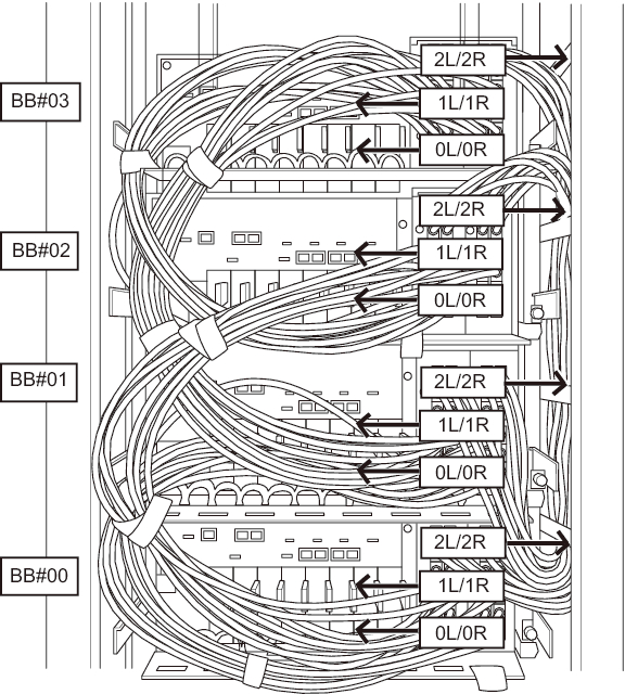
4BB configuration
For the 4BB configuration, place the crossbar cables (electrical) connected to the 2L and 2R ports of XBU#0/#1 together at the right side as viewed from the rear of the rack. Place the other crossbar cables (electrical) together at the left side as viewed from the rear of the rack.
- Hang the power cords from the left side as viewed from the rear of the rack.
Place the power cords over the cable support fixing bracket to hang them there as is.
| Note - When bundling the power cords together with hook-and-loop fastener strips, take care to secure the extra length necessary for removing the power cords inserted in the power supply units. |
- Place the crossbar cables (electrical) connected to the 0L/0R and 1L/1R ports of each XBU together at the left side as viewed from the rear of the rack.
- Secure the crossbar cables (electrical) placed together at the left side to the cable support with hook-and-loop fastener strips.
- Place the crossbar cables (electrical) connected to the 2L and 2R ports of each XBU together at the right side as viewed from the rear of the rack.
- If a cable holder is supplied with the rack used, secure the crossbar cables (electrical) placed together at the right side to the cable holder of the rack.
|
Figure 5-18 Example of stored cables (4BB configuration)
|
|
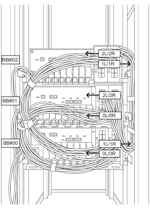
3BB configuration
For the 3BB configuration, place the crossbar cables (electrical) connected to the 1L and 1R ports of XBU#0/#1 together at the right side as viewed from the rear of the rack. Place the other crossbar cables (electrical) together at the left side as viewed from the rear of the rack.
- Hang the power cords from the left side as viewed from the rear of the rack.
Place the power cords over the cable support fixing bracket to hang them there as is.
| Note - When bundling the power cords together with hook-and-loop fastener strips, take care to secure the extra length necessary for removing the power cords inserted in the power supply units. |
- Place the crossbar cables (electrical) connected to the 0L/0R and 2L/2R ports of each XBU together at the left side as viewed from the rear of the rack.
- Secure the crossbar cables (electrical) placed together at the left side to the cable support with hook-and-loop fastener strips.
- Place the crossbar cables (electrical) connected to the 1L and 1R ports of each XBU together at the right side as viewed from the rear of the rack.
- If a cable holder is supplied with the rack used, secure the crossbar cables (electrical) placed together at the right side to the cable holder of the rack.
|
Figure 5-19 Example of stored cables (3BB configuration)
|
|
< Previous Page | Next Page >