3.4.2 Mounting the PCI expansion unit in a rack
3.4.2 Mounting the PCI expansion unit in a rack
- Confirm that the rack mount kit supplied with the PCI expansion unit is complete.
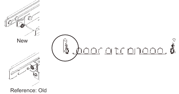
| Note - The rack mount kit contains two types of cable support: Type-1 and Type-2. To distinguish the Type-2 cable support, see Figure 3-52. The Type-2 cable support is an integrated unit consisting of the parts indicated by numbers 2 to 5 in Figure 3-51. Steps 6 and 10 in the mounting procedure vary depending on the shape of the cable support. Attach the support according to the corresponding steps. |
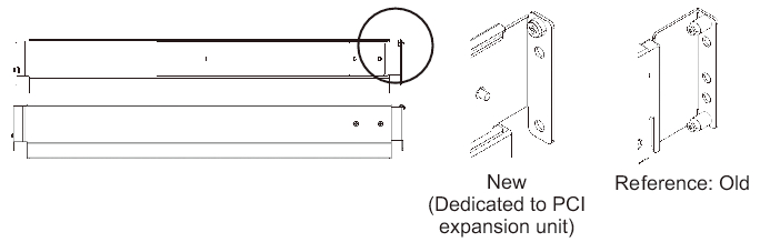
| Note - The rack mount kit contains two types of rails: Type-1 and Type-2. To distinguish the Type-2 rail, see Figure 3-53. The mounting procedure varies depending on the shape of the rail. The text describes corresponding procedures, so attach the rail according to the relevant procedure. |
|
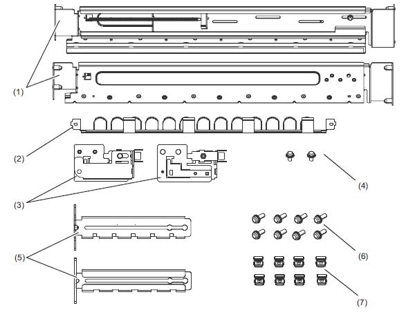
Figure 3-51 Rack mount kit
|
|
| Number in figure | Name | Quantity | Remarks |
| 1 | Rail | 2 | Bilaterally symmetrical shape |
| 2 | Cable support (*1) (*2) | 1 | |
| 3 | Cable support bracket (*2) | 2 | Bilaterally symmetrical shape |
| 4 | M3 screw (*2) | 2 | |
| 5 | Cable support fixing bracket (*2) | 2 | Bilaterally symmetrical shape |
| 6 | M6 screw | 10 | |
| 7 | Cage nut | 10 | |
| *1 There are two types of cable support: Type-1 and Type-2. To distinguish between them, see Figure 3-52. *2 The Type-2 cable support is an integrated unit consisting of these parts. |
|||
|
Figure 3-52 Type-2 cable support
|
|
|
Figure 3-53 Type-2 rail
|
|
- Confirm that the rack is secured in place to prevent the rack from toppling over.
For details, see "3.3.2 Securing the rack." - Step 3 differs depending on the shape of the supporting column holes of the rack. Perform the work appropriate to the shape of the supporting column holes of the rack.
- For racks with supporting columns having square holes
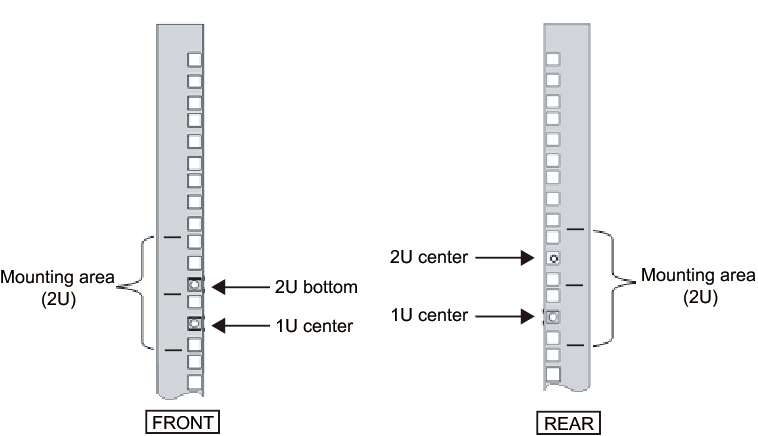
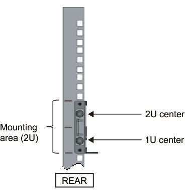
- Attach cage nuts to the left and right supporting columns of the rack.- Attachment locations in the front supporting columns: (From the bottom) 1U center and 2U bottom- Attachment locations in the rear supporting columns: (From the bottom) 1U center and 2U center
|
Figure 3-54 Cage nut attachment locations in the supporting columns of the rack
|
|
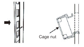
- a. Attach cage nuts from the inside of the rack.
Orient the hooks of the cage nut vertically.
Hook the hook at one end of a cage nut into a cage nut attachment hole of the rack.
Figure 3-55 shows a cage nut hooked on the lower part of a hole.
|
Figure 3-55 Orientation of the hooks of a cage nut
|
|
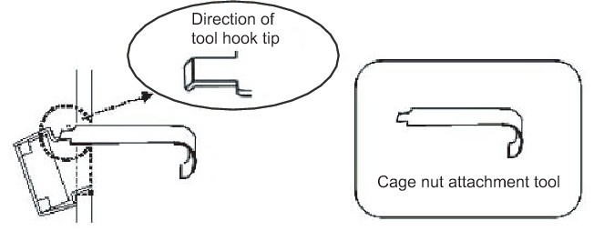
- b. Insert the hook at the tip of the supplied cage nut attachment tool through a cage nut attachment hole from the front, and engage it with the hook at the other end of the cage nut.
|
Figure 3-56 Using the cage nut attachment tool
|
|
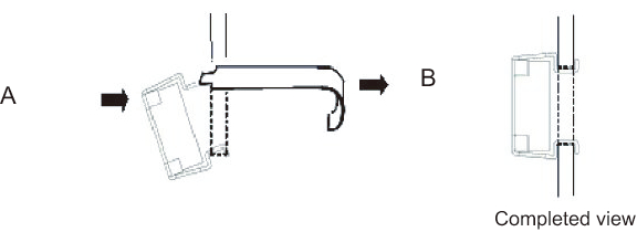
- c. Pull the tool forward to attach the cage nut.
Push in direction A while simultaneously pulling in direction B as shown in Figure 3-57.
|
Figure 3-57 Attaching a cage nut
|
|
- For supporting columns with M6 screw holes
- For the Type-1 rail
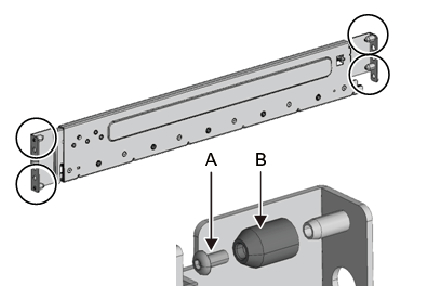
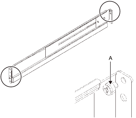
Remove the pins at the front and rear of the rail.a. Remove the screw (A in Figure 3-58) securing the rail pin.b. Remove the pin (B in Figure 3-58).c. Remove pins from the left and right rails in the same manner.d. Store the removed pins and screws (eight pins and eight screws in total) for future use when the chassis is moved.
|
Figure 3-58 Removing pins from the Type-1 rail
|
|
- For the Type-2 rail
Remove the pins at the front and rear of the rail.a. Remove the pins (A in Figure 3-59) at the front and rear of the left and right rails.b. Store the removed pins (four pins in total) for future use when the chassis is moved.
|
Figure 3-59 Removing pins from the Type-2 rail
|
|
- Remove each screw from the side of the rail.
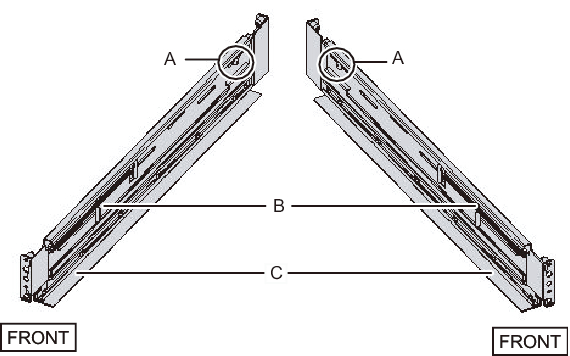
For the Type-1 rail, remove the one screw (A in Figure 3-60) from the side of the rail.
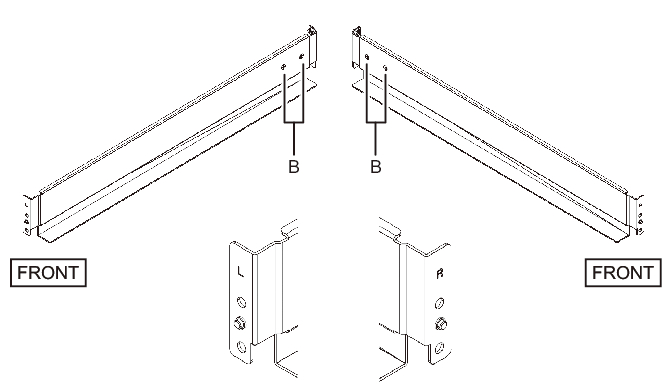
For the Type-2 rail, loosen the two screws (B in Figure 3-61) from the side of the rail.
| Note - After removing or loosening the screw or screws, hold the rail level with both hands. If the rail tilts, it may stretch. |
|
Figure 3-60 Screw on the side of the Type-1 rail
|
|
|
Figure 3-61 Screws on the side of the Type-2 rail
|
|
- Attach the rail to the rack.
| Note - After removing its screw, hold the rail level with both hands. If the rail tilts, it may stretch. |
- For the Type-1 rail
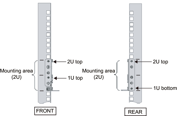
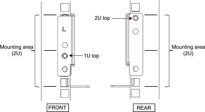
Attach the rail such that the spring-loaded side (B in Figure 3-60) faces the front and the flange (C in Figure 3-60) faces the bottom.a. From the front of the rack, insert the rail protrusions into 2U top and 1U top in the front supporting column of the rack.b. Pull out the rail to as far as the depth of the rack.c. Insert the rail protrusions into 2U top and 1U bottom in the rear supporting column of the rack.d. Secure the rail with one M6 screw to the front supporting column of the rack. The fixing location is 2U bottom.e. Attach the other rail in the same manner.
|
Figure 3-62 Attaching the Type-1 rail: Locations of protrusions
|
|
- For the Type-2 rail
The letter [R] on a side of a rail indicates that the side is the front right side, and [L] indicates that the side is the front left side.
This step differs depending on the shape of the supporting column holes of the rack. Perform the work appropriate to the shape of the supporting column holes of the rack.
- For racks with supporting columns having square holes
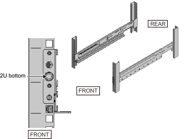
- a. From the rear of the rack, insert the rail protrusion into 1U top in the front supporting column of the rack.b. Pull out the rail to as far as the depth of the rack.c. Insert the rail protrusion into 2U top in the rear supporting column of the rack.d. Secure the rail with one M6 screw to the front supporting column of the rack. The fixing location is 2U bottom.e. Attach the other rail in the same manner.
|
Figure 3-63 Attaching the Type-2 rail: Locations of protrusions (for supporting columns having square holes)
|
|
|
Figure 3-64 Attaching the Type-2 rail: Fixing location of the screw (for supporting columns having square holes)
|
|
- For supporting columns with M6 screw holes
This work requires a total of two workers in front of and behind the rack because the rails have no protrusions and cannot be temporarily secured.
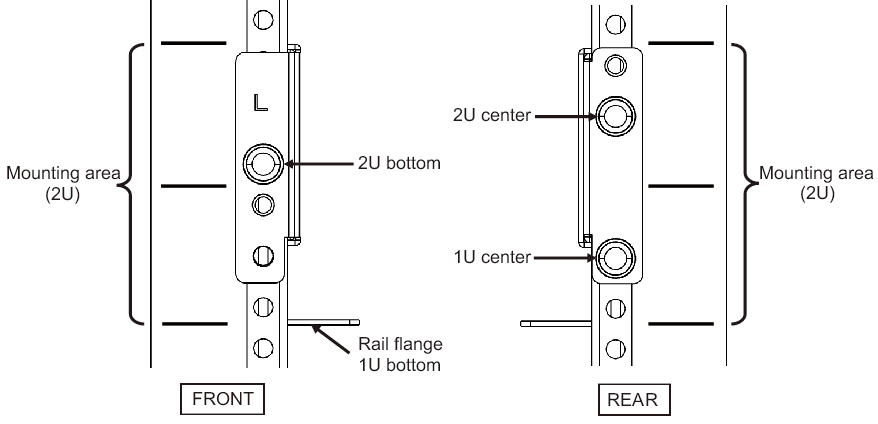
- a. From the front of the rack, vertically align the rail flange with 1U bottom in the front supporting column of the rack.b. Secure the rail with one M6 screw to the front supporting column of the rack. The fixing location is 2U bottom.c. Pull out the rail to as far as the depth of the rack.d. Secure the rail with two M6 screws to the rear supporting column of the rack. The fixing locations are 1U center and 2U center.
|
Figure 3-65 Attaching the Type-2 rail: Fixing screws (for supporting columns with M6 screw holes)
|
|
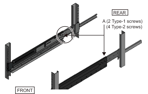
- Attach the cable support fixing brackets to the rear supporting columns of the rack.
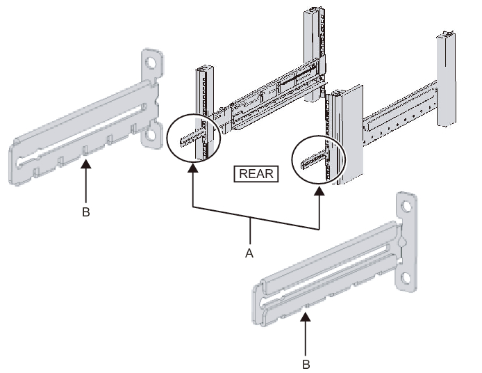
- For the Type-1 cable supporta. Orient the notches (B in Figure 3-66) on the cable support fixing brackets (A in Figure 3-66) face down.b. From the rear of the rack, secure the rails and cable support brackets with two M6 screws to the rear supporting columns of the rack.The fixing locations are 1U center and 2U center.c. After attaching the cable support bracket, confirm that the rack door can close.
| Note - If the door cannot close because the cable support fixing bracket or the cable support protrudes from the rear of the rack, do not attach the cable support bracket. However, secure the rail to the rack with two M6 screws. |
|
Figure 3-66 Attaching the cable support fixing bracket
|
|
|
Figure 3-67 Securing the cable support fixing bracket and the rail
|
|
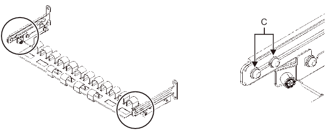
- For the Type-2 cable supporta. Loosen the four screws (C in Figure 3-68) from the inside of the cable support.
|
Figure 3-68 Removing the cable support fixing brackets (1)
|
|
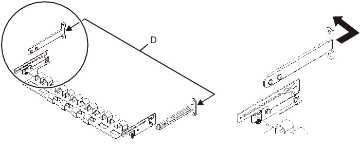
- b. Slide the cable support fixing brackets (D in Figure 3-69) to remove them.
|
Figure 3-69 Removing the cable support fixing brackets (2)
|
|
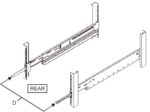
- c. From the rear of the rack, secure the rails and cable support fixing brackets (D) with two M6 screws to the rear supporting columns of the rack.The fixing locations are 1U center and 2U center.
|
Figure 3-70 Attaching the cable support brackets
|
|
|
Figure 3-71 Securing the cable support fixing bracket and the rail
|

|
- d. After attaching the cable support fixing brackets, confirm that the rack door can close.
| Note - If the door cannot close because the cable support fixing bracket or the cable support protrudes from the rear of the rack, do not attach the cable support bracket. However, secure the rail to the rack with two M6 screws. |
- Secure the side of the rail with screws (A in Figure 3-72).
For the Type-1 rail, secure the side of the rail with the screws (2 in total) removed in step 4.
For a Type-2 rail, tighten the side screws (4 in total) loosened in step 4 to secure the side of the rail.
|
Figure 3-72 Securing the sides of rails with screws
|
|
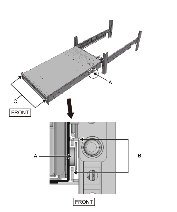
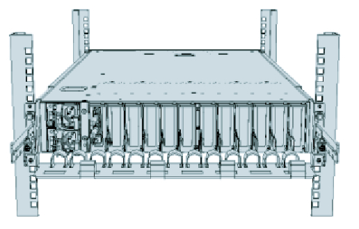
- Mount the PCI expansion unit in the rack.
Mount the chassis from the front of the rack.
|

| Note - Mount the PCI expansion unit in the rack with two or more people working together. Alternatively, use a lifter. |
- a. When using a lifter, secure it horizontally.b. Lift the chassis to the mounting location with the lifter or with human force.c. Put the rear part of the chassis on the flanges of the rails.d. Slide the PCI expansion unit into the rack. At this time, confirm that the PCI expansion unit sits on the rails and that the guide pins of the PCI expansion unit (A in Figure 3-73) fit into their rail guides (B in Figure 3-73).e. Insert the PCI expansion unit all the way to store it inside the rack.
|
Figure 3-73 Mounting in the rack
|
|
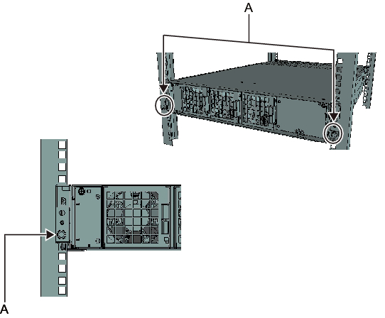
- Secure the PCI expansion unit in the rack.a. Push out the left and right slide locks on the front cover (C in Figure 3-73) to release the locks, and remove the front cover.b. Tighten the two M6 screws at two locations on the front of the PCI expansion unit (A in Figure 3-74) to secure it to the rack.c. Insert the left and right hooks on the inside of the bottom of the front cover into the grooves at the bottom front of the PCI expansion unit to attach the front cover.
| Note - A label with the serial number of the PCI expansion unit is affixed to the front cover. Be sure to attach the front cover to the corresponding chassis. |
|
Figure 3-74 Securing the PCI expansion unit
|
|
- Attach the cable support.
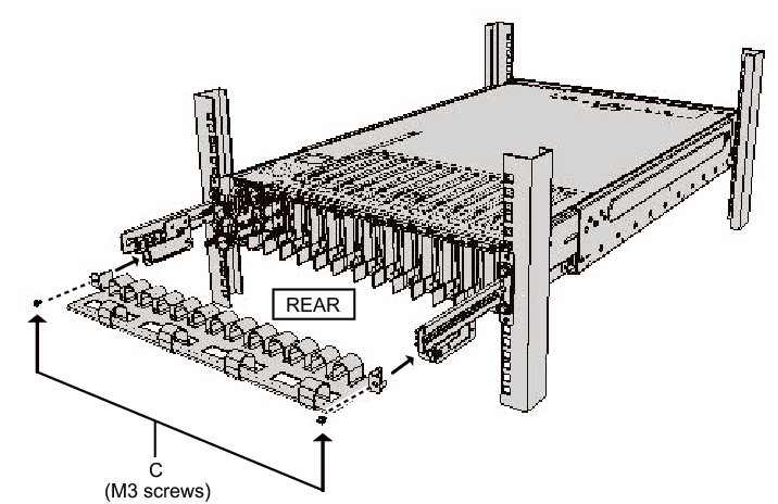
- For the Type-1 cable supporta. From the inside of the cable support fixing bracket, align the two screws in the right cable support bracket with the circular holes at the front of the groove, and attach the screws (A in Figure 3-75).b. Slide the cable support bracket toward the chassis while holding the latch (B in Figure 3-75) attached to it.c. Attach the left cable support bracket in the same manner. At this time, the left and right sides should have been slid the same amount (depth) toward the chassis.d. Secure the cable support with two M3 screws (C in Figure 3-76).e. Close the rear door of the rack, and confirm that the cable support brackets do not interfere. If it interferes, slide the cable support toward the chassis while holding the latches (B in Figure 3-75) of the left and right cable support brackets. The cable support should be in the position nearest the chassis, with the cable support bracket latches engaged.f. If the cable support interferes with the door even when you slide it toward the chassis as far as possible, remove the cable support.
|
Figure 3-75 Attaching the cable support brackets
|
|
|
Figure 3-76 Attaching the cable support
|
|
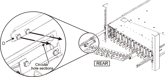
- For the Type-2 cable supporta. Tilt the cable support to align the circular holes at the rear of the groove with the two screws of a cable support fixing bracket (D in Figure 3-77), and attach it. Level the cable support. Then, align the circular holes at the other side with the two screws, and attach it.
|
Figure 3-77 Attaching the cable support (1)
|
|
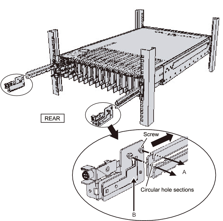
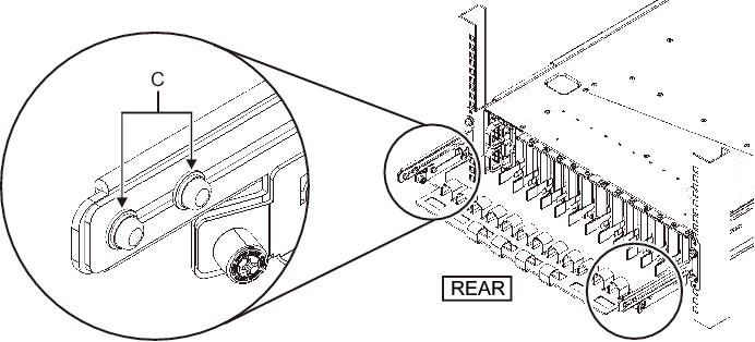
- b. Slide in the cable support all the way, and tighten the four screws (C in Figure 3-78).
|
Figure 3-78 Attaching the cable support (2)
|
|
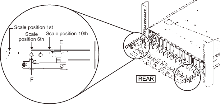
| Note - If the dimension between the front and rear columns of the rack is less than 740 mm, secure the cable support without sliding it in all the way. The fixing location varies depending on the dimension between the front and rear columns of the rack. Based on Figure 3-79, align the scale marks (E in Figure 3-79) (spacing: 10 mm) on the cable support with the screws (F in Figure 3-79) of the fixing brackets to secure the cable support. |
|
Figure 3-79 Attaching the cable support (3)
|
|
| Dimension between front and rear columns (mm) | Scale position |
|---|---|
| 740 | 1st |
| 730 | 2nd |
| 720 | 3rd |
| 710 | 4th |
| 700 | 5th |
| 690 | 6th |
| 680 | 7th |
| 670 | 8th |
| 660 | 9th |
| 650 | 10th |
| Note - If you have difficulty laying a thick cable into the cable support, move forward the fixing location of the cable support to make the work easier. |
- c. Close the rear door of the rack, and confirm that the cable support does not interfere. If the cable support interferes with the rear door, remove the cable support. Even if you remove the cable support, leave the rails secured with the two M6 screws to the rack.
|
Figure 3-80 Completed cable support attachment
|
|
|
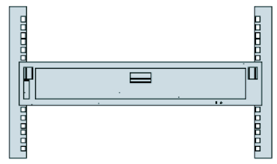
Figure 3-81 Completed PCI expansion unit configuration
|
|
< Previous Page | Next Page >