5.2 Connecting Cables to the PCI Expansion Unit
5.2 Connecting Cables to the PCI Expansion Unit
This section describes the procedure for connecting the management cable, link cables, and power cords to the PCI expansion unit.
- Connect the management cable.
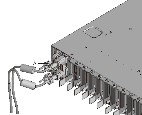
Connect the link board of the PCI expansion unit and the link card of the chassis by using the management cable. (See A in Figure 5-9 and A in Figure 5-10.)
- Connect link cables.
Connect the cables such that the port indications on the link card and link board match the labels on the cables.
Each port on the link card and link board is color-coded and numbered. Connect the port to the corresponding port of the same color and number.
| Note - The two link cables are the same. The labels on both ends of each cable have the same indications. When laying the cables, check their connections to confirm that the ends of the cables connected to the link card and link board are at the same ports shown on the labels. |
|
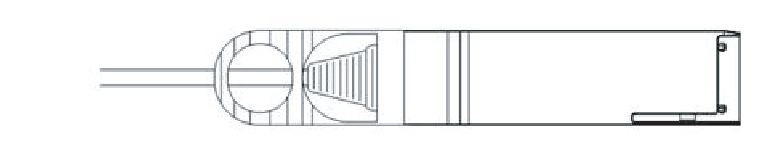
Figure 5-8 Link cable (optical) shape
|
|
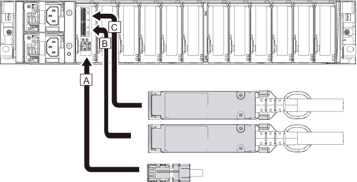
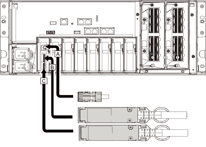
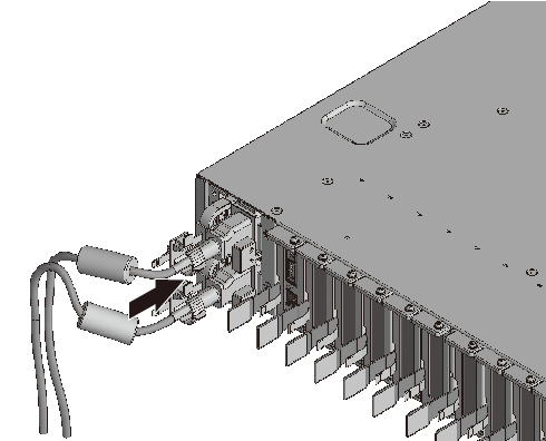
- a. Connect one end of a link cable to the port (B in Figure 5-9) on the link board mounted in the PCI expansion unit.b. Connect the other end to the port (B in Figure 5-10) on the link card of the SPARC M10-4S.c. Connect one end of the other link cable to the port (C in Figure 5-9) on the link board mounted in the PCI expansion unit.d. Connect the other end to the port (C in Figure 5-10) on the link card of the SPARC M10-4S.
| Note - The two ports have the same shape and so may be incorrectly connected. Check the labels at both ends of each cable to confirm that the cable is connected to the correct ports. Hold the connector of the link cable (electrical) or link cable (optical), and insert it straight into the opening. Do not hold the cable or its tab part when inserting it. |
| Note - PCIe cassettes are mounted upside down in the SPARC M10-4S and the PCI expansion unit. Accordingly, the port locations of PCIe cards, including the link card, are also upside down. Be careful about this when mounting the cables. |
|
Figure 5-9 Connecting the link cables and management cable (PCI expansion unit side)
|
|
|
Figure 5-10 Connecting the link cables and management cable (SPARC M10-4S side)
|
|
- If a PCIe card is mounted, connect a LAN cable and I/O cable to the respective ports on the PCIe card.
- Secure the cables to the cable support.
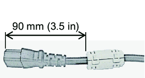
While leaving extra length, secure the cables connected to the PCIe card to the cable support. - Attach a core to each supplied power cord, and connect the cord to a power supply unit.a. Insert the power cord so that it fits into the groove of the core. Pinch the core closed until its latch is secured.
Attach the core at a location 90 mm (3.5 in) from the end of the power cord connector. (See Figure 5-11.)
|
Figure 5-11 Core attachment location
|
|
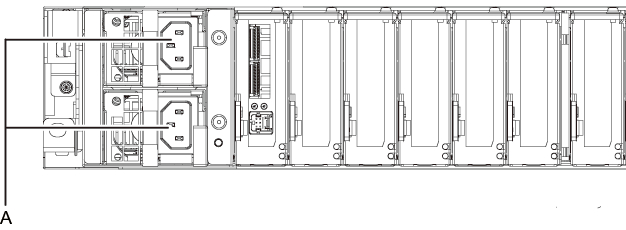
- b. Insert the power cord straight into the power supply unit (A in Figure 5-12) all the way.
|
Figure 5-12 Power supply unit locations
|
|
| Note - Do not connect to an outlet at this point. |
|
Figure 5-13 Attaching power cords
|
|
- c. Secure the power cords with cable clamps.
After locking each clasp (A in Figure 5-14), push the cable clamp toward the front of the chassis to firmly secure the clamp.~>~
|
Figure 5-14 Locking a cable clamp
|
|
< Previous Page | Next Page >