5.4.3 Expansion rack
5.4.3 Expansion rack
For an expansion rack, keep the power cords together at the left side and the other cables at the right side as viewed from the rear of the rack.
| Note - For an expansion rack, crossbar cables (optical) and XSCF cables are stored in the rack at the time of shipping. For details on connections, see "4.3 Connecting Cables (for Connections through Crossbar Boxes)." |
- Hang the power cords from the left side as viewed from the rear of the rack.
According to the following procedure, connect the power cords of the SPARC M10-4S mounted in the expansion rack to the PDUs, and lay the power cords.a. Connect the power cords to the PDUs as instructed by the destination labels.
See the power connection diagram appropriate to your power input type in "2.8 Checking the Power Input Type" about the placements of PDUs and their connections with the respective SPARC M10-4S to connect the power cords.
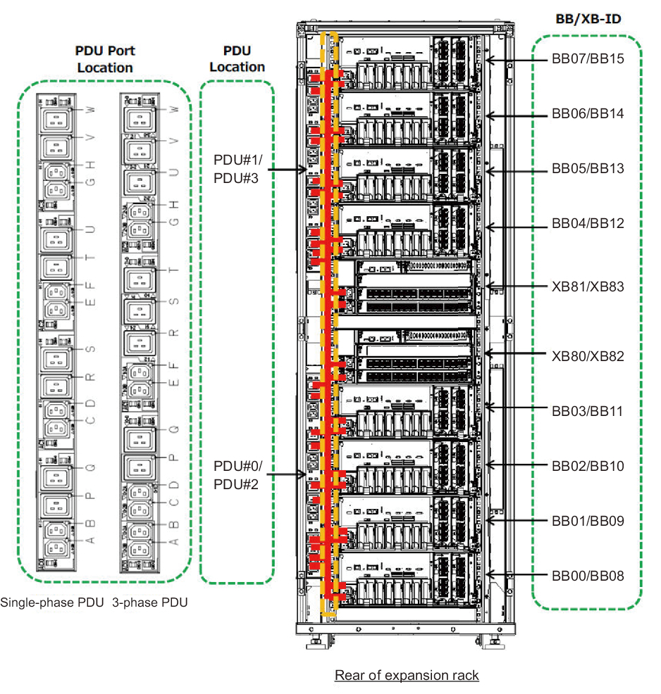
For the SPARC M10-4S and PDU locations to connect with the power cords, see Figure 5-20.
|
Figure 5-20 Power cord wiring diagram
|
|
|
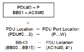
Figure 5-21 Example of the appearance of a power cord label
|
|
- b. Use the space between a SPARC M10-4S and PDU to lay the extra length of power cords after wiring, and use the supplied hook-and-loop fastener strips to bundle them.
| Note - When bundling the power cords together with hook-and-loop fastener strips, take care to secure the extra length necessary for removing the power cords inserted in the power supply units. |
< Previous Page | Next Page >