2.4.5 Bottom view of an expansion rack
2.4.5 Bottom view of an expansion rack
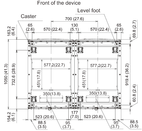
Figure 2-10 shows the locations of openings for taking out/in cables, the leveling feet, and the casters on the bottom of the expansion rack. This top-view diagram shows the bottom of the inside of the expansion rack as viewed from directly above.
Note that the values shown are expansion unit design values. To fix the leveling feet to the floor, determine locations allowing for a tolerance of ±2 mm (±0.1 in.), which is the dimensional tolerance of the expansion racks.
|
Figure 2-10 Bottom view of an expansion rack, Unit: mm (in.)
|
|
< Previous Page | Next Page >