9.2.3 Adding the server after turning off the input power to the entire system
9.2.3 Adding the server after turning off the input power to the entire system
This section describes the procedure for adding the SPARC M10-4S after stopping the entire system while work is in progress and turning off the input power.
For details on the XSCF commands executed in each step, see the Fujitsu SPARC M12 and Fujitsu M10/SPARC M10 XSCF Reference Manual.
For details on the XSCF commands executed in each step, see the Fujitsu SPARC M12 and Fujitsu M10/SPARC M10 XSCF Reference Manual.
| Note - Suppose you add the SPARC M10-4S together with a PCI expansion unit connected to it and enable/disable the direct I/O function of the PCI expansion unit. Then, at the next startup, the logical domain configuration of the physical partition resets to the factory-default state. See "1.7.2 Notes on Using the Direct I/O Function" and "1.7.3 How to Save/Restore the Logical Domain Configuration Information and the OpenBoot PROM Environment Variable" in the PCI Expansion Unit for Fujitsu SPARC M12 and Fujitsu M10/SPARC M10 Service Manual and take action. |
- Log in to the master XSCF.
- Execute the showsscp command to check whether the IP address of the SP to SP communication protocol (SSCP) is a default value or a value set by a user.
| XSCF> showsscp |
| Note - For the default values of SSCP IP addresses, see "3.9.5 Understanding the IP Addresses that are Set with SSCP" in the Fujitsu SPARC M12 and Fujitsu M10/SPARC M10 System Operation and Administration Guide. |
- If the IP address is a default value and the default value should also be used for the IP address of the SPARC M10-4S to be added, go to the next step.
To set a user value, use the setsscp command to set an IP address, use the applynetwork command to apply the SSCP IP address of the target SPARC M10-4S, and confirm that it was reflected. Then, execute the rebootxscf command to complete settings, and go to the next step. For details on the step, see "3.9.15 Reflecting the XSCF Network Settings" in the Fujitsu SPARC M12 and Fujitsu M10/SPARC M10 System Operation and Administration Guide.
- Check the number of CPU Activations registered in the entire system.
If the number of CPU Activations registered in the system becomes short compared to the number of added CPU cores, purchase a CPU Activation key and execute the addcodactivation command to add the key to the system.
The following example displays the CPU Activations in the system that are already fully used.
| XSCF> showcodusage -p resource Resource In Use Installed CoD Permitted Status -------- ------ --------- ------------- ------ PROC 64 64 64 OK |
- For details on adding a CPU Activation key, see "7.11.3 Registering a CPU Activation key."
- Execute the poweroff command to stop the system.
| XSCF> poweroff -y -a |
- Remove the power cords of all the chassis from the input power.
- Mount the target SPARC M10-4S in the rack.
For the mounting procedure, see "3.4.1 Mounting the SPARC M10-4S in a rack."
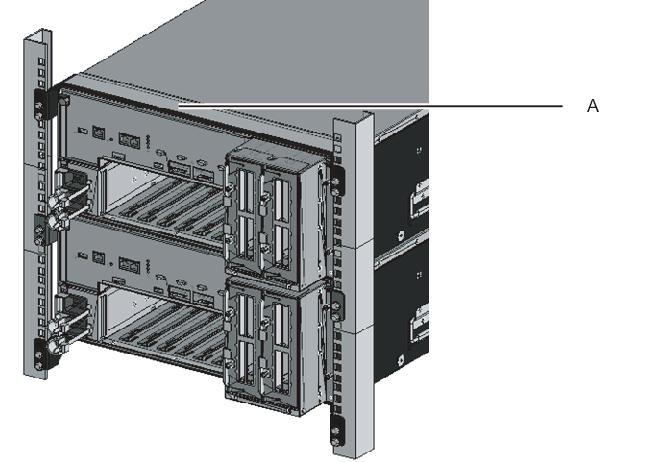
| Remarks - When adding the SPARC M10-4S in an existing expansion rack, you need to remove the protection bracket and blank panel of the mounting space (A in Figure 9-3). Note that there are cases where no protection bracket is attached, depending on the addition. The blank panel is secured with two M6 screws. The protection bracket is secured with four M6 screws. |
|
Figure 9-3 Protection bracket
|
|
- Set the ID of the target SPARC M10-4S.
For details, see "4.1 Setting the ID (BB-ID) Identifying a Chassis." - Connect the additional crossbar cables.
For a cable routing diagram of connections and a cable list, see "Appendix B Cable Connection Information on Building Block Configurations."
For details on the connections in direct connections between chassis, see "4.2 Connecting Cables (for Direct Connections between Chassis)."
| Remarks - For connections through crossbar boxes, the additional crossbar cables (optical) are secured to the expansion rack. When packed, the cables are tied to a rack column with their connectors wrapped in a bag. Remove the cable connectors from the rack column and unpack them. For details, see Figure 4-13. |
- Connect the additional XSCF BB control cables.
For a cable routing diagram of connections and a cable list, see "Appendix B Cable Connection Information on Building Block Configurations."
For details on the connections in direct connections between chassis, see "4.2 Connecting Cables (for Direct Connections between Chassis)." - If the addition expands the 1BB configuration to up to the 4BB configuration with direct connections between chassis, connect the XSCF DUAL control cable.
For details, see "4.2 Connecting Cables (for Direct Connections between Chassis)." - Connect LAN cables to the target SPARC M10-4S.
For details, see "5.1 Connecting Cables to the SPARC M10-4S." - Connect the power cords of all the chassis to the input power.
- Log in to the master XSCF.
| Note - If the message of "XSCF firmware update now in progress. BB#xx,please wait for XSCF firmware update complete." is output after login, the XCP firmware version is automatically being matched. Execute the showlogs monitor command to confirm the message of "XCP firmware version synchronization completed," and then perform the next work. |
- Execute the version command.
Confirm the XCP versions. If any chassis has a different version, update it so that all the versions are the same.
- The following example shows a building block configuration of the SPARC M10-4S. Here, BB#02 has a different XCP version, so it must be updated to match the version. Perform step 14.
| XSCF> version -c xcp BB#00-XSCF#0 (Master) XCP0 (Current): 2051 XCP1 (Reserve): 2051 BB#01-XSCF#0 (Standby) XCP0 (Current): 2051 XCP1 (Reserve): 2051 BB#02-XSCF#0 XCP0 (Current): 2050 * Different version XCP1 (Reserve): 2050 |
- If the XCP version of a chassis differs, execute the flashupdate -c sync command to update the XCP version on that chassis.
The update matches the firmware version to the version on the XSCF of the master chassis. If you want to match the version of the latest XCP, update XCP on the master chassis to the latest version in advance, or update the XCP firmware here.
For the firmware update procedure, see "Chapter 16 Updating the XCP Firmware" in the Fujitsu SPARC M12 and Fujitsu M10/SPARC M10 System Operation and Administration Guide.
| XSCF> flashupdate -c sync XCP update is started. [3600sec] 0..... 30..... 60..... 90.....120.....150.....180.....210.....240..... 270.....300.....330.....360.....390.....420.....450.....480.....510..... |
- Execute the testsb command to perform a diagnosis test.
<Description of options specified>-v: Additionally displays detailed messages of the initial diagnosis-p: Executes the "probe-scsi-all" command of OpenBoot PROM and displays the results while a diagnosis is being processed-s: Executes the "show-devs" command of OpenBoot PROM and displays the results while a diagnosis is being processed-a: Diagnoses all the mounted PSBs-y: Automatically responds with "y" to a query
| XSCF> testsb -v -p -s -a -y Initial diagnosis is about to start, Continue?[y|n] :y PSB power on sequence started. POST Sequence 01 Banner |
- If an error is displayed, see "A.2.4 Checking diagnosis results."
| Note - A cable check with the diagxbu command is not necessary because this command with the -a option specified performs a diagnosis test on all the mounted system boards (PSBs). |
- Execute the showlogs error command, and confirm that no error is displayed.
| XSCF> showlogs error |
- If an error is displayed, see "A.2.2 Checking the contents of logs."
- Execute the showhardconf command from the master XSCF to check the configuration, status, and quantities.
For details, see "6.8 Checking the Component Status." - If the addition expanded the 1BB configuration to a multiple-BB configuration, configure the XSCF network.
For details, see "7.5.2 Setting an Ethernet (XSCF-LAN) IP address" and "7.5.3 Setting a takeover IP address."
After configuration, execute the applynetwork command to apply the settings, and confirm that they were reflected. Then, execute the rebootxscf command to complete settings, and go to the next step. For details on the procedure, see "7.5.6 Applying network settings." - To configure memory mirroring for the added SPARC M10-4S, set memory mirror mode.
For details, see "7.6 Configuring Memory Mirroring." - Create physical partition configuration information.
For details, see "7.7 Creating a Physical Partition Configuration List (PCL)." - Add the system board (PSB) to the physical partition.
For details, see "7.8 Assigning a System Board (PSB) to a Physical Partition (PPAR)."
- Set the number of CPU Activations in the physical partition, and add CPU core resources.a. Execute the showcodusage command to display the CPU Activation information.The following example displays the CPU Activation information.
The system here has 192 CPU core resources installed and 192 CPU Activations registered. The example shows that the CPU core resources are not in use and that the 192 CPU Activations are currently not in use.
| XSCF> showcodusage -p resource Resource In Use Installed CoD Permitted Status -------- ------ --------- ------------- ------ PROC 0 192 192 OK: 192 cores available Note: Please confirm the value of the "In Use" by the ldm command of Oracle VM Server for SPARC. The XSCF may take up to 20 minutes to reflect the "In Use" of logical domains. |
- b. Execute the showcod command to check the CPU Activation information set for the physical partition.
| XSCF> showcod -p 0 PROC Permits assigned for PPAR 0: 64 |
- c. If the assigned resources are insufficient, execute the setcod command to assign CPU resources to the physical partition.The following example adds 64 CPU core resources to physical partition 0.
| XSCF> setcod -p 0 -s cpu -c add 64 PROC Permits assigned for PPAR 0 : 128 -> 192 PROC Permits assigned for PPAR will be changed. Continue? [y|n] :y Completed. |
| Note - The -c add, -c delete, and -c set options are not supported if the XSCF firmware is XCP 2250 or earlier. Specify the option of the setcod command as shown below to add or delete interactively. |
| XSCF> setcod -s cpu |
- d. Execute the showcod command again to check the CPU Activation information set for the physical partition.
| XSCF> showcod -p 0 PROC Permits assigned for PPAR 0: 192 |
- Execute the poweron command to start the system.
| XSCF> poweron -y -a |
- Execute the showpparstatus command to check the operation status of the physical partition.
In the following example, the [PPAR Status] field displays "Running," so the physical partition is operating correctly.
| XSCF> showpparstatus -p 0 PPAR-ID PPAR Status 00 Running |
- Execute the showboards command to check the system board (PSB) status.
In the following example, since both the [Conn] and [Conf] fields display "y" for system board 02-0, the system board (PSB) has been added correctly.
| XSCF> showboards -p 0 PSB PPAR-ID(LSB) Assignment Pwr Conn Conf Test Fault ---- ------------ ----------- ---- ---- ---- ------- -------- 00-0 00(00) Assigned y y y Passed Normal 01-0 00(01) Assigned y y y Passed Normal 02-0 00(02) Assigned y y y Passed Normal |
- Reconfigure the logical domains.
Assign the resources of the added SPARC M10-4S to an existing logical domain or a newly configured logical domain. For details, see the Fujitsu SPARC M12 and Fujitsu M10/SPARC M10 Domain Configuration Guide.
< Previous Page | Next Page >