10.2.1 Removing the server while the target physical partition (PPAR) is operating
10.2.1 Removing the server while the target physical partition (PPAR) is operating
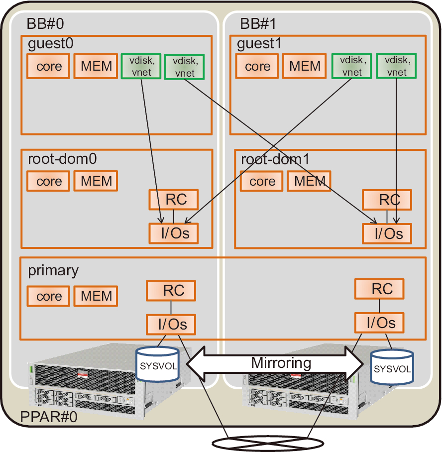
This section describes the removal procedure on the system in "Figure 10-1 2BB configuration example" from a 2BB configuration to a 1BB configuration while the target physical partition (PPAR) is in operation. To perform maintenance while the physical partition (PPAR) is operating, use dynamic reconfiguration (DR) for the physical partition.
For the software requirements required for this operation, see the latest Fujitsu M10/SPARC M10 Systems Product Notes and Oracle VM Server for SPARC 3.2 Administration Guide.
For the software requirements required for this operation, see the latest Fujitsu M10/SPARC M10 Systems Product Notes and Oracle VM Server for SPARC 3.2 Administration Guide.
For details on the XSCF commands executed in each step, see the Fujitsu SPARC M12 and Fujitsu M10/SPARC M10 XSCF Reference Manual.
|
Figure 10-1 2BB configuration example
|
|
- Log in to the master XSCF.
Execute the showbbstatus command to confirm that the XSCF to which you have logged in is the master XSCF.
If it is a standby XSCF, retry to log in to the master XSCF.
| XSCF> showbbstatus BB#00 (Master) |
- Execute the showhardconf command, and confirm the chassis serial number of the system board (PSB) targeted for release.
For details, see "A.2.1 Checking the component status."
| Note - If the serial number of the target chassis is being used as the system serial number, the initbb command cannot release the chassis. In this case, execute the switchscf command to switch the master XSCF. |
- Execute the console command to connect to the console of the control domain, and then log in.
| XSCF> console -p 0 |
- Check the operation status and the resource use status of logical domains.
- a. Execute the ldm list-domain command to check the operation status of the logical domains.Check the operation status of the logical domains through the combination of [STATE] and [FLAGS]. When [STATE] is "active," the second character from the left of the string in [FLAGS] has one of the following meanings:"n": Oracle Solaris operating"t": OpenBoot PROM state"-": Another state (including cases in which [STATE] is not "active")In this example, you can see that the control domain, two guest domains, and two root domains are operating.
| # ldm list-domain NAME STATE FLAGS CONS VCPU MEMORY UTIL UPTIME primary active -n-cv- UART 16 14G 0.0% 10h 7m guest0 active -n---- 5100 32 32G 0.0% 2h 20s guest1 active -n---- 5101 32 32G 0.0% 2h 5s root-dom0 active -n--v- 5000 24 24G 0.0% 2h 43s root-dom1 active -n--v- 5001 24 24G 0.0% 2h 20s |
- b. Execute the ldm list-devices command with the -a option specified to check the resource use status.The following example specifies the -a option to display all the resources bound to logical domains and all those not bound to logical domains.
| # ldm list-devices -a CORE ID %FREE CPUSET 0 0 (0, 1) 4 0 (8, 9) 8 0 (16, 17) (Omitted) 184 0 (368, 369) 188 100 (376, 377) 512 100 (1024, 1025) 516 100 (1032, 1033) 520 100 (1040, 1041) 524 100 (1048, 1049) (Omitted) VCPU PID %FREE PM 0 0 no 1 0 no 8 0 no 9 0 no (Omitted) 369 0 no 376 100 --- 377 100 --- 1024 100 --- 1025 100 --- 1032 100 --- 1033 100 --- (Omitted) |
- Release redundant configurations of system volumes and I/O devices of the control domain.
This example shows the procedure to release the I/O device of the SPARC M10-4S to be removed that is used in the control domain so that the building block BB-ID#01 can be released. If other redundant software is in use, see the document of each redundant software for details on the procedure to release the configuration.
- a. Release redundant configurations of system volumes of the control domain.The following example shows the procedure to release the ZFS mirror function of system volumes of the control domain.a-1) Execute the zpool status command on the control domain to check the state of the mirror configuration.
| # zpool status rpool pool: rpool state: ONLINE scan: resilvered 28.7M in 0h0m with 0 errors on Tue Jan 21 10:10:01 2014 config: NAME STATE READ WRITE CKSUM rpool ONLINE 0 0 0 mirror-0 ONLINE 0 0 0 c2t50000393E802CCE2d0s0 ONLINE 0 0 0 c3t50000393A803B13Ed0s0 ONLINE 0 0 0 errors: No known data errors |
- a-2) Execute the zpool detach command to release the disk from the mirror configuration.
| # zpool detach rpool c3t50000393A803B13Ed0 |
- a-3) Execute the zpool status command to confirm that the mirror configuration is released.
| # zpool status rpool pool: rpool state: ONLINE scan: resilvered 28.7M in 0h0m with 0 errors on Tue Jan 21 10:10:01 2014 config: NAME STATE READ WRITE CKSUM rpool ONLINE 0 0 0 mirror-0 ONLINE 0 0 0 c2t50000393E802CCE2d0s0 ONLINE 0 0 0 errors: No known data errors |
- If there are any other devices on BB#01 in use, release the redundant configurations and stop using the devices. For how to release the redundant configurations and how to stop using the devices, refer to the documents of software in the redundant configurations and Oracle Solaris.
- b. Delete the I/O configuration of the control domain.b-1) Out of the physical I/O devices assigned to the control domain, delete the root complex of BB#01.
- b-2) Change the control domain to the delayed reconfiguration mode.This operation is not required if the root complexes are reconfigured dynamically.The following shows the software conditions to reconfigure the root complexes dynamically.- XCP 2240 or later- Oracle VM Server for SPARC 3.2 or later- Oracle Solaris 11.2 SRU11.2.8 or later
| # ldm start-reconf primary Initiating a delayed reconfiguration operation on the primary domain. All configuration changes for other domains are disabled until the primary domain reboots, at which time the new configuration for the primary domain will also take effect. |
- b-3) Execute the ldm list-io command to check the root complexes assigned to the primary domain.The following example tells that the root complexes with the device of BB1 are PCIE8 and PCIE12.
| # ldm list-io | grep primary PCIE0 BUS PCIE0 primary IOV PCIE4 BUS PCIE4 primary IOV PCIE8 BUS PCIE8 primary IOV PCIE12 BUS PCIE12 primary IOV /BB0/CMUL/NET0 PCIE PCIE0 primary OCC /BB0/CMUL/SASHBA PCIE PCIE0 primary OCC /BB0/CMUL/NET2 PCIE PCIE4 primary OCC /BB1/CMUL/NET0 PCIE PCIE8 primary OCC /BB1/CMUL/SASHBA PCIE PCIE8 primary OCC /BB1/CMUL/NET2 PCIE PCIE12 primary OCC |
- b-4) Execute the ldm remove-io command to delete PCIE8 and PCIE12 from the domain "primary".
| # ldm remove-io PCIE8 primary # ldm remove-io PCIE12 primary |
- b-5) Restart Oracle Solaris.This operation is not required if the root complexes are reconfigured dynamically.
| # shutdown -i6 -g0 -y |
- b-6) Execute the ldm list-io command to confirm that the root complexes of BB#01 are deleted from the control domain.
| # ldm list-io | grep primary PCIE0 BUS PCIE0 primary IOV PCIE4 BUS PCIE4 primary IOV /BB0/CMUL/NET0 PCIE PCIE0 primary OCC /BB0/CMUL/SASHBA PCIE PCIE0 primary OCC /BB0/CMUL/NET2 PCIE PCIE4 primary OCC |
- c. Release the redundant configurations of virtual I/O devices assigned to the guest domain.To shut down the root domain (root-dom1) with the root complexes of BB#01 assigned before deleting the I/O devices, log in to each guest domain and release the redundant configuration of the virtual I/O device from root-dom1.For details on how to use software in redundant configurations, see the document of each software in the redundant configuration.
- The following shows an example of releasing the virtual network device (vnet1) from the configuration of IPMP. For command details, see the Oracle Solaris manual.c-1) Log in to the guest domain (guest0).
| # ldm list-domain NAME STATE FLAGS CONS VCPU MEMORY UTIL UPTIME primary active -n-cv- UART 64 56G 0.0% 4h 17m guest0 active -n---- 5100 64 64G 0.0% 1h 13m guest1 active -n---- 5101 64 64G 0.0% 1h 4m root-dom0 active -n--v- 5000 32 32G 0.0% 1h 47m root-dom1 active -n--v- 5001 32 32G 0.0% 1h 19m # telnet localhost 5100 .... guest0# |
- c-2) Execute the dladm show-phys command to check the correspondence between the virtual network interface (vnet1) and the network interface name (net1).
- c-3) Execute the ipmpstat -i command to confirm the configuration information of the network interface that configures IPMP.
| guest0# ipmpstat -i INTERFACE ACTIVE GROUP FLAGS LINK PROBE STATE net0 yes ipmp0 -smbM-- up disabled ok net1 no ipmp0 is----- up disabled ok guest0# if_mpadm -d net1 guest0# ipmpstat -i INTERFACE ACTIVE GROUP FLAGS LINK PROBE STATE net0 yes ipmp0 -smbM-- up disabled ok net1 no ipmp0 -s---d- up disabled offline |
- c-4) Execute the if_mpadm -d command, release net1 from the IPMP group, and execute the ipmpstat -i command to confirm that net1 is released. In the next example, confirm that STATE becomes offline.Perform the same release work on the guest domain (guest1).
| guest1# if_mpadm -d net1 guest1# ipmpstat -i INTERFACE ACTIVE GROUP FLAGS LINK PROBE STATE net0 yes ipmp0 -smbM-- up disabled ok net1 no ipmp0 -s---d- up disabled offline |
- d. Delete the virtual I/O devices assigned from the root domain to be stopped.Execute the ldm remove-vdisk command and the ldm remove-vnet command, and perform the following procedure to delete the virtual disk (vdisk) and the virtual network device (vnet) assigned from the root domain to be stopped.The following shows an example of executing the command to delete the virtual disk (vdisk11) and the virtual network device (vnet10) that uses the virtual I/O service of the BB#01 root domain (root1-dom1).
| # ldm remove-vdisk vdisk11 guest0 # ldm remove-vnet vnet10 guest0 |
- Perform the same deletion work on the guest domain (guest1).
- Check the resource use status of the I/O devices and release all the I/O devices of the SPARC M10-4S to be removed.
- a. Confirm the logical domain where the root complexes of the SPARC M10-4S to be released are assigned.Execute the ldm list-io command to check the logical domain where the root complexes of BB#01 are assigned.In the next example, only root-dom1 owns the PCIe end point that starts with "/BB1/". Then, PCIE9, PCIE10, PCIE11, PCIE13, PCIE14, and PCIE15, which are the root complexes (BUS) of the PCIe end point, are assigned to root-dom1.
| # ldm list-io NAME TYPE BUS DOMAIN STATUS ---- ---- --- ------ ------ PCIE0 BUS PCIE0 primary IOV PCIE1 BUS PCIE1 root-dom0IOV PCIE2 BUS PCIE2 root-dom0IOV PCIE3 BUS PCIE3 root-dom0IOV PCIE4 BUS PCIE4 primary IOV PCIE5 BUS PCIE5 root-dom0IOV PCIE6 BUS PCIE6 root-dom0IOV PCIE7 BUS PCIE7 root-dom0IOV PCIE8 BUS PCIE8 PCIE9 BUS PCIE9 root-dom1IOV PCIE10 BUS PCIE10 root-dom1IOV PCIE11 BUS PCIE11 root-dom1IOV PCIE12 BUS PCIE12 PCIE13 BUS PCIE13 root-dom1IOV PCIE14 BUS PCIE14 root-dom1IOV PCIE15 BUS PCIE15 root-dom1IOV .... /BB1/CMUL/NET0 PCIE PCIE8 UNK /BB1/CMUL/SASHBA PCIE PCIE8 UNK /BB1/PCI0 PCIE PCIE9 root-dom1OCC /BB1/PCI3 PCIE PCIE10 root-dom1OCC /BB1/PCI4 PCIE PCIE10 root-dom1OCC /BB1/PCI7 PCIE PCIE11 root-dom1OCC /BB1/PCI8 PCIE PCIE11 root-dom1OCC /BB1/CMUL/NET2 PCIE PCIE12 UNK /BB1/PCI1 PCIE PCIE13 root-dom1OCC /BB1/PCI2 PCIE PCIE13 root-dom1OCC /BB1/PCI5 PCIE PCIE14 root-dom1OCC /BB1/PCI6 PCIE PCIE14 root-dom1OCC /BB1/PCI9 PCIE PCIE15 root-dom1OCC /BB1/PCI10 PCIE PCIE15 root-dom1OCC |
- b. Stop and release the root domain where the root complexes of the SPARC M10-4S to be released are assigned.In the next example, we can confirm that the ldm stop-domain command and the ldm unbind-domain command are executed, the root domain (root-dom1) is released, and the root domain enters the inactive state.
| # ldm stop-domain root-dom1 LDom root-dom1 stopped # ldm unbind-domain root-dom1 # ldm list-domain NAME STATE FLAGS CONS VCPU MEMORY UTIL UPTIME primary active -n-cv- UART 16 14G 0.2% 4h 59m guest0 active -n---- 5100 32 32G 0.0% 1h 55m guest1 active -n---- 5101 32 32G 0.0% 1h 46m root-dom0 active -n--v- 5000 24 24G 0.0% 2h 29m root-dom1 inactive ------ 24 24G |
- c. Confirm all the I/O devices of the building block to be removed are released.Execute the ldm list-io command to confirm that the I/O devices are released.
| # ldm list-io NAME TYPE BUS DOMAIN STATUS ---- ---- --- ------ ------ PCIE0 BUS PCIE0 primary IOV PCIE1 BUS PCIE1 root-dom0IOV PCIE2 BUS PCIE2 root-dom0IOV PCIE3 BUS PCIE3 root-dom0IOV PCIE4 BUS PCIE4 primary IOV PCIE5 BUS PCIE5 root-dom0IOV PCIE6 BUS PCIE6 root-dom0IOV PCIE7 BUS PCIE7 root-dom0IOV PCIE8 BUS PCIE8 PCIE9 BUS PCIE9 PCIE10 BUS PCIE10 PCIE11 BUS PCIE11 PCIE12 BUS PCIE12 PCIE13 BUS PCIE13 PCIE14 BUS PCIE14 PCIE15 BUS PCIE15 (Omitted) |
- Go back to the XSCF shell and confirm the system board status of the SPARC M10-4S to be removed.
Execute the showboards command to check the system board status.
Confirm that the system board of the SPARC M10-4S to be removed is in the Assigned state and "y" is displayed for all of the [Pwr], [Conn], and [Conf] columns.
| XSCF> showboards -p 0 PSB PPAR-ID(LSB) Assignment Pwr Conn Conf Test Fault ---- ------------ ----------- ---- ---- ---- ------- -------- 00-0 00(00) Assigned y y y Passed Normal 01-0 00(01) Assigned y y y Passed Normal |
- Release the system board from the physical partition.
- a. Execute the deleteboard command to release the system board (PSB) from the physical partition.The following example releases system board 01-0 from the physical partition to be in the system board pool.
| XSCF> deleteboard -c unassign 01-0 PSB#01-0 will be unassigned from PPAR immediately. Continue?[y|n] :y Start unconfigure preparation of PSB. [1200sec] 0end Unconfigure preparation of PSB has completed. Start unconfiguring PSB from PPAR. [43200sec] 0..... 30.end Unconfigured PSB from PPAR. PSB power off sequence started. [1200sec] 0..... 30..... 60..... 90.....120.....150.end Operation has completed. |
| Note - In releasing the system board (PSB) by the deleteboard command, the hardware resource on the system board (PSB) is released from Oracle Solaris. Therefore, the command execution may take some time to complete. |
- b. Execute the showresult command to confirm the end status of the previously executed deleteboard command.In the following example, 0 is returned as the end status, so the execution of the deleteboard command has completed correctly.
| XSCF> showresult 0 |
- c. Execute the showboards command to check the system board (PSB) status.In the following example, system board 01-0 is in the system board pool.
| XSCF> showboards -p 0 PSB PPAR-ID(LSB) Assignment Pwr Conn Conf Test Fault ---- ------------ ----------- ---- ---- ---- ------- -------- 00-0 00(00) Assigned y y y Passed Normal 01-0 SP Available n n n Passed Normal |
- Execute the ldm list-domain command on the control domain console of the physical partition, and confirm that the operation status of the logical domains has not changed after the system board (PSB) deletion.
- Execute the initbb command from the master XSCF to release the target SPARC M10-4S from the system and initialize it.
In bb_id, specify the ID (BB-ID) identifying the chassis.
| XSCF> initbb -b bb_id |
| Note - After the execution of the initbb command, the target chassis is released from the system and enters the stopped state. Do not disconnect the power cords or various cables until the XSCF STANDBY LED on the panel and the rear READY LED of the target chassis are off. |
- Remove the power cords from the power supply units of the target SPARC M10-4S.
- Remove the XSCF BB control cables from the target SPARC M10-4S.
- Remove the crossbar cables from the target SPARC M10-4S.
| Note - Do not hold the cable part when pulling out the crossbar cable. Pulling the cable part without the connector lock completely released may cause damage. |
- You are performing removal to the 1BB configuration. So, remove the XSCF DUAL control cable.
- Remove the target SPARC M10-4S from the rack.
Remove the SPARC M10-4S from the rack by reversing the mounting procedure. For the procedure for mounting in the rack, see "3.4.1 Mounting the SPARC M10-4S in a rack."
The removed SPARC M10-4S enters the factory default status because the initbb command is executed. If you want to use it as another system, see "1.1 Workflow for the SPARC M10-4S" to perform installation.
< Previous Page | Next Page >