4.3.1 Connecting XSCF cables
4.3.1 Connecting XSCF cables
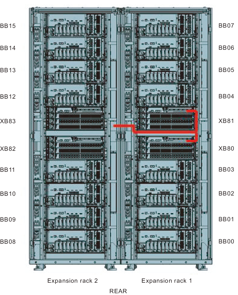
Cables that pass between racks are secured to expansion rack 2. Connect cables to their respective ports on expansion rack 1 through the empty space in the connecting part of the racks.
For the cable routes, see Figure 4-8.
When laying the cables, use the supplied hook-and-loop fastener strips to bundle them as appropriate.
For the cable routes, see Figure 4-8.
When laying the cables, use the supplied hook-and-loop fastener strips to bundle them as appropriate.
- Pass the XSCF BB control cables stored in expansion rack 2 through the upper side of the connecting part of the racks (B in Figure 4-14).
- Connect the XSCF BB control cables.
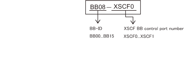
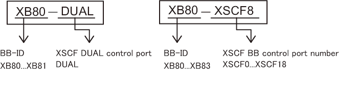
Each cable has an attached label showing the connection destination port. Connect the cable to the port corresponding to the label. - Check the connection of the XSCF DUAL control cable.
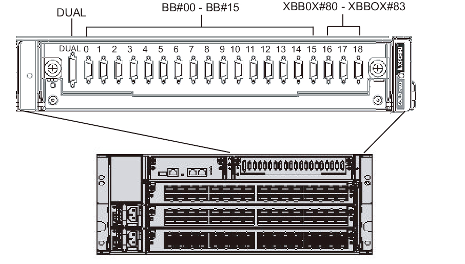
Confirm that the cable is connected between the XSCF DUAL control port of XBBOX#80 and the XSCF DUAL control port of XBBOX#81.
|
Figure 4-8 Cable laying diagram
|
|
|
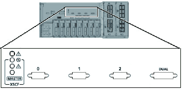
Figure 4-9 XSCF port locations (SPARC M10-4S side)
|
|
|
Figure 4-10 XSCF interface unit port locations (crossbar box side)
|
|
|
Figure 4-11 Example of the appearance of an XSCF cable label (SPARC M10-4S side)
|
|
|
Figure 4-12 Examples of the appearance of an XSCF cable label (crossbar box side)
|
|
< Previous Page | Next Page >