2.4.1 Mounting conditions for general racks
2.4.1 Mounting conditions for general racks
1BB configuration/4BB configuration with direct connections between chassis
The SPARC M10-4S is designed for mounting in an equipment rack.
If the SPARC M10-4S units are connected by cables, mount the units side by side in a rack with no gap between them.
If the SPARC M10-4S units are connected by cables, mount the units side by side in a rack with no gap between them.
|
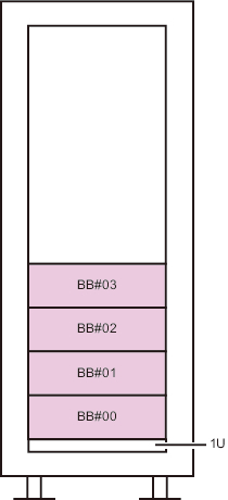
Figure 2-3 Chassis mounting locations (corresponding to BB-IDs) for the 4BB configuration
|
|
| Note - For SPARC M10-4S maintenance, the cable support at the chassis rear moves underneath the chassis, so do not mount anything in the lowest shelf (1U) of the rack. |
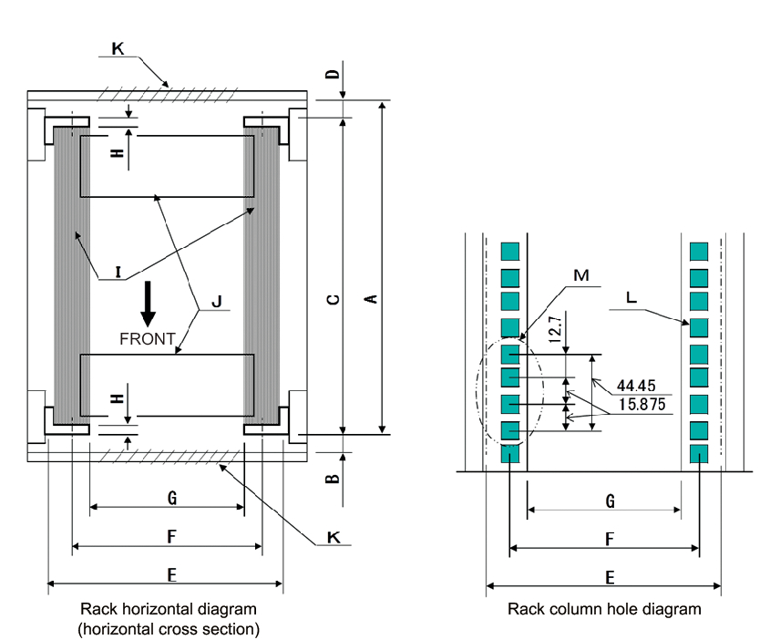
For mounting in a third-party rack, it is the customer's responsibility to confirm that the rack specifications match the specifications and requirements for the SPARC M10 systems (see Figure 2-4 and Table 2-3).
|
Figure 2-4 Dimensional drawings for third-party rack checks
|
|
| Note - The dimensions shown in the conditions do not include any protrusions. |
| Description | Condition | Letter in figure |
|---|---|---|
| Rack type/Compliance standards | Equipment rack/EIA standard-compliant | -- |
| Dimension between rear door (inside) and front column | SPARC M10-4S: At least 930 mm (36.6 in.) PCI-BOX: At least 848 mm (33.4 in.) |
A |
| Dimension between front door (inside) and front column | SPARC M10-4S: At least 32 mm (1.3 in.) PCI-BOX: At least 24 mm (0.9 in.) |
B |
| Dimension between front and rear columns | Within adjustment range of rack mount kit Adjustment range of the mount kit for each server SPARC M10-4S: 630 mm (24.8 in.) to 840 mm (33.1 in.) PCI-BOX: 630 mm (24.8 in.) to 840 mm (33.1 in.) |
C |
| Dimension between rear door (inside) and rear column | SPARC M10-4S: At least 158 mm (6.2 in.) PCI-BOX: At least 158 mm (6.2 in.) |
D |
| Front panel mounting space of chassis | At least 483 mm (19.0 in.) | E |
| Distance between left and right chassis attachment holes (common to front and rear columns) | 465 mm (18.3 in.) |
F |
| Distance between left and right columns (common to front and rear columns) | At least 450 mm (17.7 in.) | G |
| Column thickness | 2 mm (0.08 in.) to 2.5 mm (0.1 in.) |
H |
| Structures other than columns | Rack has no structures between front and rear columns | I |
| Cable hatch | Rack has hatch on bottom surface, rear door, or elsewhere | J |
| Area of door vent openings | Front door: At least 73 % of door area Rear door: At least 73 % of door area |
K |
| Size of attachment holes (common to front and rear columns) | Square hole with sides longer than 9.2 mm (0.36 in.) and not longer than 9.8 mm (0.38 in.) (*1) or M6 screw hole | L |
| Vertical pitch of chassis attachment holes (common to front and rear columns) |
EIA standards, universal pitch | M |
| Door opening angle | Door opens to 130° | -- |
| Strength | Rack has necessary strength/load capacity for mounting chassis | -- |
| Grounding | Rack and units can be grounded | -- |
| Toppling prevention measures | Rack can be prevented from toppling over | -- |
| Earthquake resistance measures | Earthquake resistance measures can be implemented for rack | -- |
| *1 If the SPARC M10-4S or PCI expansion unit has angled holes with sides of 9.0 mm (0.35 in.) to 9.2 mm (0.36 in.), a separate rack mount kit must be ordered. | ||
- Mounting on the lowest shelf of the rack
For the SPARC M10-4S, the cable support at the chassis rear moves underneath the chassis during maintenance, so do not mount the chassis on the lowest shelf (1U) of the rack. (See Figure 2-3) - Other conditions
In addition to structural conditions, the following condition must be taken into consideration.- Install the rack such that the temperature inside the rack meets the temperature conditions for cooling the chassis when mounted in the rack. For details, see "2.5 Checking Environmental Conditions." Particularly, make sure that exhaust from the chassis does not re-enter the chassis through the air intakes. This requires measures such as covering the front and rear of empty spaces inside the rack.
< Previous Page | Next Page >