3.3.3 Connecting racks
3.3.3 Connecting racks
In a configuration with expansion rack 2, connect racks directly. To connect the racks, connect a rack to the already installed rack (expansion rack 1).
|

|

This section describes the procedure for connecting expansion rack 2 to the right side of expansion rack 1.
- Confirm that the connecting kit supplied with expansion rack 2 is complete.
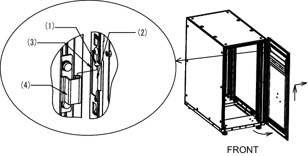
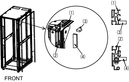
- Remove the front doors of expansion racks 1 and 2.a. Open the door about 90°.b. Lifting up the door, remove the hinge (pin) on the main body of the rack. Then, slide the door laterally to remove it.
|
|
Figure 3-17 Removing the front door
|
|
| Number in figure | Description |
|---|---|
| 1 | Hinge on door |
| 2 | Notch for hinge |
| 3 | Bend for controlling opening and closing angle |
| 4 | Hinge on main body |
- Remove the rear doors of expansion racks 1 and 2.a. Open the door about 90°.b. Lifting up the door, remove the hinge (pin) on the main body of the rack. Then, slide the door laterally to remove it.
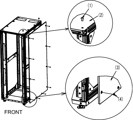
- Remove the screws securing the top cover of expansion rack 1, and remove the side plate.a. Use an Allen wrench to remove the two M12 screws securing the top cover, at the front and rear on the right side, which is the connecting side. The removed screws will not be used.b. Remove the 10 screws securing the side plate, and remove the side plate.
| Note - Be careful because work on the top cover section is done high off the ground. Never do anything dangerous such as putting your foot on the rack, which would be very dangerous. |
| Note - Be careful when removing the side plate because it weighs about 13 kg. |
|
Figure 3-18 Removing the side plate
|
|
| Number in figure | Description |
|---|---|
| 1 | M12 screw |
| 2 | Top cover |
| 3 | Side plate |
| 4 | Screw |
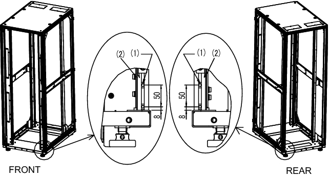
- Attach M6 core spring nuts to the front and rear of expansion rack 1.a. Attach two M6 core spring nuts in the lower part of the vertical column (right side as viewed from the front) on the connecting side at the front of the rack.b. Attach two M6 core spring nuts in the lower part of the vertical column (left side as viewed from the rear) on the connecting side at the rear of the rack.
|
Figure 3-19 Attaching core spring nuts
|
|
| Number in figure | Description |
|---|---|
| 1 | M6 core spring nut |
| 2 | Vertical column |
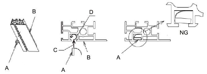
- Procedure for attaching core spring nuts
Perform work by referring to Figure 3-20.a. Insert core spring nut A in direction C into the groove of vertical column B. Then, rotate it in direction D.
Use the tip of a pen or a fine flat-bladed screwdriver, etc. to help you do this.b. Confirm that the core spring nut is not inclined in the groove of the aluminum frame.
| Note - Check whether the screw section of the core spring nuts can be seen from outside of the groove. |
|
Figure 3-20 Attaching core spring nuts
|
|
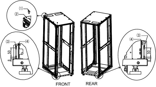
- Affix connecting packings.a. Affix vertical connecting packings 1 and 2 to the front and rear vertical columns on the right side of expansion rack 1. You can affix either of them at the top.
For the locations for affixing the connecting packings, see (4) in Figure 3-21.b. Affix the horizontal connecting packings to the horizontal column on the upper right side of expansion rack 1.
For the locations for affixing the connecting packings, see (3) in Figure 3-21.
|
Figure 3-21 Affixing connecting packings
|
|
| Number in figure | Description |
|---|---|
| 1 | Horizontal column |
| 2 | Vertical column |
| 3 | Horizontal connecting packing |
| 4 | Vertical connecting packing |
- Remove the screws securing the top cover of expansion rack 2, and attach M6 core spring nuts to the front and rear of the rack.a. Use an Allen wrench to remove the two M12 screws securing the top cover, at the front and rear on the left side, which is the connecting side.
| Note - Be careful because work on the top cover section is done high off the ground. Never do anything dangerous such as putting your foot on the rack, which would be very dangerous. |
- b. Attach two M6 core spring nuts in the lower part of the vertical column (left side as viewed from the front) on the connecting side at the front of the rack.c. Attach two M6 core spring nuts in the lower part of the vertical column (right side as viewed from the rear) on the connecting side at the rear of the rack.
|
Figure 3-22 Attaching core spring nuts (expansion rack 2 side)
|
|
| Number in figure | Description |
|---|---|
| 1 | M12 screw |
| 2 | Top cover |
| 3 | M6 core spring nut |
| 4 | Vertical column |
- Align the heights of expansion racks 1 and 2.a. Arrange expansion rack 2 next to expansion rack 1.b. Adjust the leveling feet of expansion rack 2 to align its height with that of expansion rack 1.
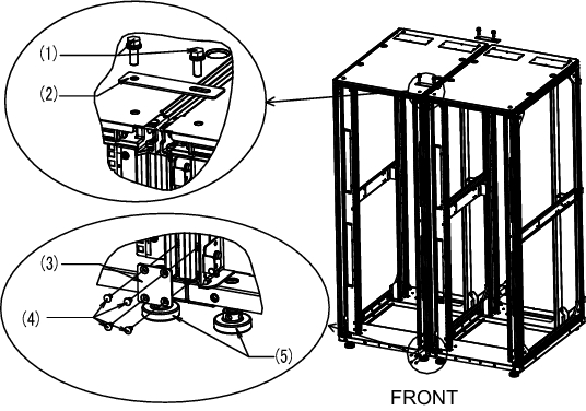
- Attach the upper and lower connecting brackets.a. Align the upper connecting brackets with the top covers of expansion racks 1 and 2, and temporarily join them using M12 hexagon head bolts.
| Note - Confirm that the heights of expansion racks 1 and 2 are aligned. If not, adjust the heights by using the leveling feet. |
| Note - Be careful because work on the top cover section is done high off the ground. Never do anything dangerous, such as putting your foot on the rack, which would be very dangerous. |
| Note - If a connecting packing protrudes or is recessed when you align expansion racks 1 and 2, adjust it by pulling or pushing it with your fingers. |
| Note - Before attaching the connecting brackets, confirm that the cables stored in the expansion rack 2 are packed. After the connecting brackets are secured, it may not be possible to remove the cables that pass between the racks. As needed, unpack the cables that pass between the racks, and pass them to expansion rack 1 (see 4.3) so that they can be taken out. For details on unpacking and packing location, see "4.3.2 Connecting crossbar cables." |
- b. Using the M6 core spring nuts attached to the front and rear vertical columns of the rack in steps 5 and 7, secure the lower connecting brackets with M6 flat-head screws.c. Finally, tighten the M12 hexagon head bolts for securing the upper connecting brackets that have temporarily joined the racks.
|
Figure 3-23 Attaching connecting brackets
|
|
| Number in figure | Description |
|---|---|
| 1 | M12 hexagon head bolt |
| 2 | Upper connecting bracket |
| 3 | Lower connecting bracket |
| 4 | M6 flat-head screw |
| 5 | Leveling foot |
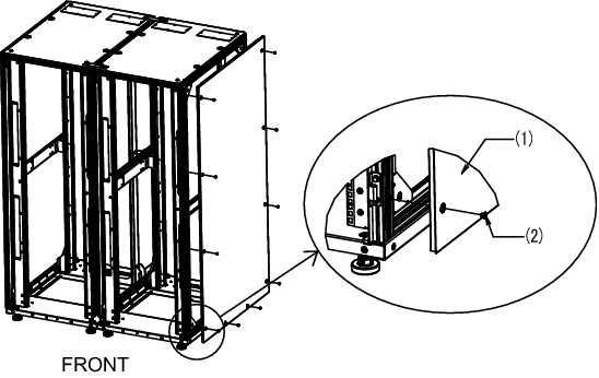
- Attach the side plate to expansion rack 2.
Attach the side plate removed from expansion rack 1 with the 10 screws of the side plate removed from expansion rack 1.
| Note - Be careful when attaching the side plate because it weighs about 13 kg. |
|
Figure 3-24 Attaching the side plate
|
|
| Number in figure | Description |
|---|---|
| 1 | Side plate |
| 2 | Screw |
- Attach the front and rear doors of expansion racks 1 and 2.
The work of connecting the racks ends when the front and rear doors are attached.
< Previous Page | Next Page >