4.3.3 Changing crossbar cables (when subsequently installing expansion rack 2)
4.3.3 Changing crossbar cables (when subsequently installing expansion rack 2)
When subsequently installing expansion rack 2, you need to change the connections of crossbar cables (optical). This work is not necessary during the initial installation.
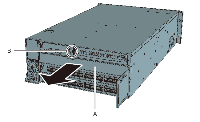
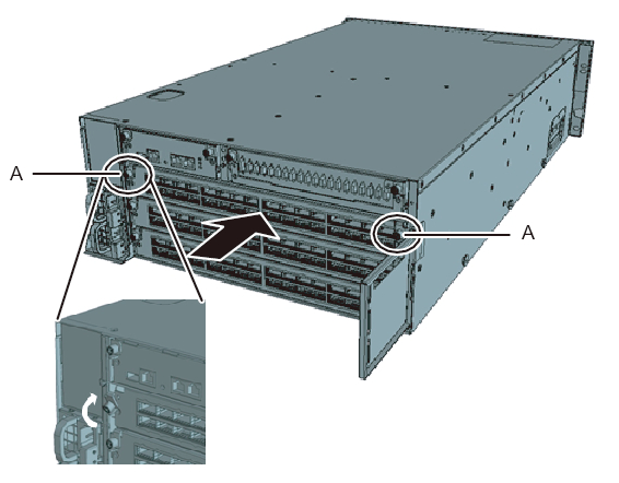
- Mount a crossbar unit in XBBOX#80/#81.a. Remove the one screw (B in Figure 4-21) securing the blank panel.b. Remove the blank panel (A in Figure 4-21) from slot #2, where the crossbar unit is to be installed.c. Insert the crossbar unit into slot #2. The crossbar unit is supplied with expansion rack 2.d. Close the left and right levers of the crossbar unit, and tighten two screws (A in Figure 4-22).
|
Figure 4-21 Removing the blank panel
|
|
|
Figure 4-22 Mounting the crossbar unit
|
|
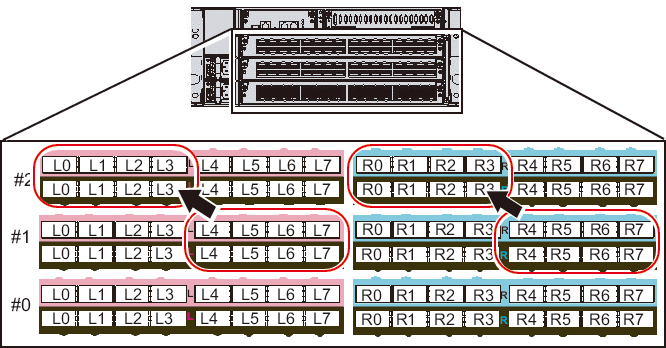
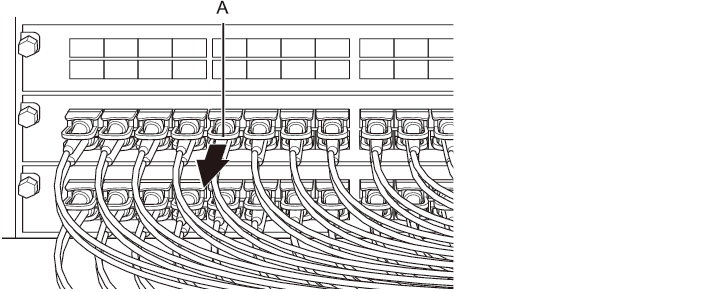
- Move the crossbar cables (optical) of XBBOX#80/#81.a. Remove the crossbar cables (optical) from L4 to L7 and from R4 to R7 of crossbar unit #1 (see Figure 4-23). Hold the tab (A in Figure 4-24) of the crossbar cable (optical) and pull it straight out in the direction of the arrow to remove the cable.
| Note - Do not hold the cable part when pulling out the crossbar cable. Pulling the cable part without the connector lock completely released may cause damage. |
|
Figure 4-23 Moving cables of XBBOX#80/#81
|
|
|
Figure 4-24 Crossbar cable (optical) tab and pulling direction
|
|
- b. Replace the labels on the removed crossbar cables (optical). The replacement labels are supplied with expansion rack 2. Referring to Table 4-1, replace the labels.
| Before change | After change | |||
|---|---|---|---|---|
| XB80-XBU1-L4 | Pink | -> |
XB80-XBU2-L0 | Pink |
| XB80-XBU1-L4 | Black | -> |
XB80-XBU2-L0 | Black |
| XB80-XBU1-L5 | Pink | -> |
XB80-XBU2-L1 | Pink |
| XB80-XBU1-L5 | Black | -> |
XB80-XBU2-L1 | Black |
| XB80-XBU1-L6 | Pink | -> |
XB80-XBU2-L2 | Pink |
| XB80-XBU1-L6 | Black | -> |
XB80-XBU2-L2 | Black |
| XB80-XBU1-L7 | Pink | -> |
XB80-XBU2-L3 | Pink |
| XB80-XBU1-L7 | Black | -> |
XB80-XBU2-L3 | Black |
| XB80-XBU1-R4 | Light blue | -> |
XB80-XBU2-R0 | Light blue |
| XB80-XBU1-R4 | Black | -> |
XB80-XBU2-R0 | Black |
| XB80-XBU1-R5 | Light blue | -> |
XB80-XBU2-R1 | Light blue |
| XB80-XBU1-R5 | Black | -> |
XB80-XBU2-R1 | Black |
| XB80-XBU1-R6 | Light blue | -> |
XB80-XBU2-R2 | Light blue |
| XB80-XBU1-R6 | Black | -> |
XB80-XBU2-R2 | Black |
| XB80-XBU1-R7 | Light blue | -> |
XB80-XBU2-R3 | Light blue |
| XB80-XBU1-R7 | Black | -> |
XB80-XBU2-R3 | Black |
| XB81-XBU1-L4 | Pink | -> |
XB81-XBU2-L0 | Pink |
| XB81-XBU1-L4 | Black | -> |
XB81-XBU2-L0 | Black |
| XB81-XBU1-L5 | Pink | -> |
XB81-XBU2-L1 | Pink |
| XB81-XBU1-L5 | Black | -> |
XB81-XBU2-L1 | Black |
| XB81-XBU1-L6 | Pink | -> |
XB81-XBU2-L2 | Pink |
| XB81-XBU1-L6 | Black | -> |
XB81-XBU2-L2 | Black |
| XB81-XBU1-L7 | Pink | -> |
XB81-XBU2-L3 | Pink |
| XB81-XBU1-L7 | Black | -> |
XB81-XBU2-L3 | Black |
| XB81-XBU1-R4 | Light blue | -> |
XB81-XBU2-R0 | Light blue |
| XB81-XBU1-R4 | Black | -> |
XB81-XBU2-R0 | Black |
| XB81-XBU1-R5 | Light blue | -> |
XB81-XBU2-R1 | Light blue |
| XB81-XBU1-R5 | Black | -> |
XB81-XBU2-R1 | Black |
| XB81-XBU1-R6 | Light blue | -> |
XB81-XBU2-R2 | Light blue |
| XB81-XBU1-R6 | Black | -> |
XB81-XBU2-R2 | Black |
| XB81-XBU1-R7 | Light blue | -> |
XB81-XBU2-R3 | Light blue |
| XB81-XBU1-R7 | Black | -> |
XB81-XBU2-R3 | Black |
- c. Connect crossbar cables (optical) from L0 to L3 and from R0 to R3 of crossbar unit #2.
Mount the crossbar cables (optical) according to the labels.
Hold the connector of the crossbar cable (optical), and insert it straight into the opening.
Do not hold the cable or its tab part when inserting it.
| Note - If you insert the connector with the tab pulled back, you may damage the connector. |
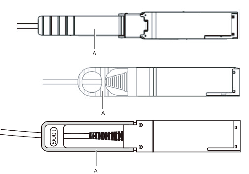
| Note - There are three types of crossbar cable (optical). Connect a crossbar cable (optical) of the same type to ports of the same port number. You can distinguish the type of crossbar cable (optical) by the tab shape (A in Figure 4-25). |
|
Figure 4-25 Crossbar cable (optical) shapes and tabs
|
|
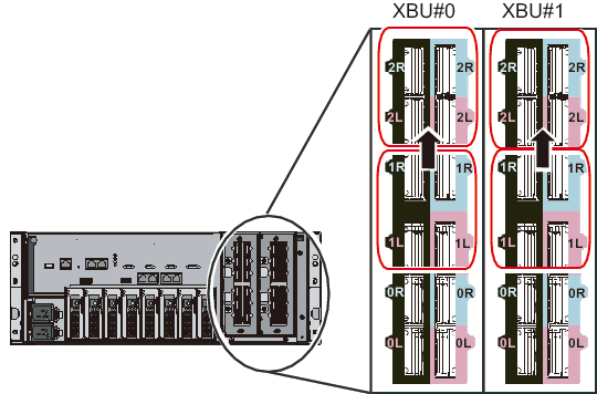
- Move the BB#07 crossbar cables (optical) from BB#04.a. Remove the crossbar cables (optical) from 1L and 1R of crossbar unit #0/#1.
|
Figure 4-26 Moving BB#07 cables from BB#04
|
|
- b. Replace the labels on the removed crossbar cables (optical).
The replacement labels are supplied with expansion rack 2. Referring to Table 4-2, replace the labels.
| Before change | After change | |||
|---|---|---|---|---|
| BB04-XBU0-1L | Pink | -> |
BB04-XBU0-2L | Pink |
| BB04-XBU0-1L | Black | -> |
BB04-XBU0-2L | Black |
| BB04-XBU0-1R | Light blue | -> |
BB04-XBU0-2R | Light blue |
| BB04-XBU0-1R | Black | -> |
BB04-XBU0-2R | Black |
| BB04-XBU1-1L | Pink | -> |
BB04-XBU1-2L | Pink |
| BB04-XBU1-1L | Black | -> |
BB04-XBU1-2L | Black |
| BB04-XBU1-1R | Light blue | -> |
BB04-XBU1-2R | Light blue |
| BB04-XBU1-1R | Black | -> |
BB04-XBU1-2R | Black |
| BB05-XBU0-1L | Pink | -> |
BB05-XBU0-2L | Pink |
| BB05-XBU0-1L | Black | -> |
BB05-XBU0-2L | Black |
| BB05-XBU0-1R | Light blue | -> |
BB05-XBU0-2R | Light blue |
| BB05-XBU0-1R | Black | -> |
BB05-XBU0-2R | Black |
| BB05-XBU1-1L | Pink | -> |
BB05-XBU1-2L | Pink |
| BB05-XBU1-1L | Black | -> |
BB05-XBU1-2L | Black |
| BB05-XBU1-1R | Light blue | -> |
BB05-XBU1-2R | Light blue |
| BB05-XBU1-1R | Black | -> |
BB05-XBU1-2R | Black |
| BB06-XBU0-1L | Pink | -> |
BB06-XBU0-2L | Pink |
| BB06-XBU0-1L | Black | -> |
BB06-XBU0-2L | Black |
| BB06-XBU0-1R | Light blue | -> |
BB06-XBU0-2R | Light blue |
| BB06-XBU0-1R | Black | -> |
BB06-XBU0-2R | Black |
| BB06-XBU1-1L | Pink | -> |
BB06-XBU1-2L | Pink |
| BB06-XBU1-1L | Black | -> |
BB06-XBU1-2L | Black |
| BB06-XBU1-1R | Light blue | -> |
BB06-XBU1-2R | Light blue |
| BB06-XBU1-1R | Black | -> |
BB06-XBU1-2R | Black |
| BB07-XBU0-1L | Pink | -> |
BB07-XBU0-2L | Pink |
| BB07-XBU0-1L | Black | -> |
BB07-XBU0-2L | Black |
| BB07-XBU0-1R | Light blue | -> |
BB07-XBU0-2R | Light blue |
| BB07-XBU0-1R | Black | -> |
BB07-XBU0-2R | Black |
| BB07-XBU1-1L | Pink | -> |
BB07-XBU1-2L | Pink |
| BB07-XBU1-1L | Black | -> |
BB07-XBU1-2L | Black |
| BB07-XBU1-1R | Light blue | -> |
BB07-XBU1-2R | Light blue |
| BB07-XBU1-1R | Black | -> |
BB07-XBU1-2R | Black |
- c. Connect the crossbar cables (optical) to 2L and 2R of crossbar unit #0/#1.
Mount the cables according to the labels.
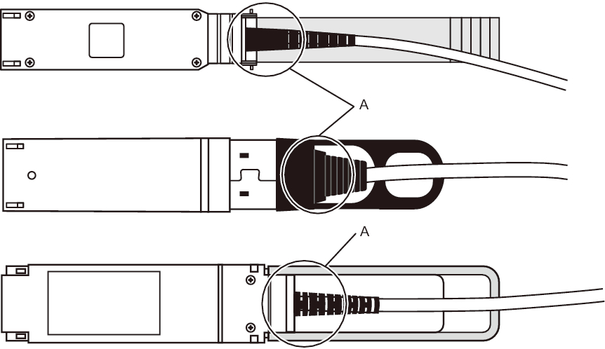
- Confirm that the crossbar cables (optical) are correctly and firmly connected.
With the crossbar cables (optical) connected to their ports, push in each cable while holding the joint (A in Figure 4-27) at the base of the connector of the crossbar cable (optical).
| Note - A loose crossbar cable connection may, on rare occasions, cause an error due to poor connection. After connecting a crossbar cable, push it in again so that it is tightly in place to prevent any improper connection. Do not hold only the cable when performing work at this time. Otherwise, the cable may bend out of shape. |
|
Figure 4-27 Part to hold when checking a crossbar cable (optical) connection
|
|
< Previous Page | Next Page >