4.2.2 Connecting crossbar cables
4.2.2 Connecting crossbar cables
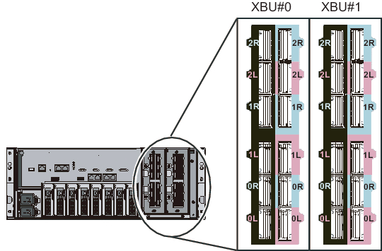
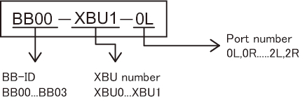
Although the connection route varies depending on the BB configuration, the connection method is the same. Each cable has an attached label showing the connection destination port. Connect the cable to the port corresponding to the label. There are two ports with the same port number. Each port on the chassis is color-coded. Connect the port to the corresponding port of the same color. For port locations and examples of the appearance of the label, see Figure 4-5 and Figure 4-6.
The descriptions in this section use the 2BB configuration as an example.
The descriptions in this section use the 2BB configuration as an example.
| Note - The crossbar cables (electrical) are connected from the XBU#1 side at the chassis rear in units of four cables. For the connection order, see "Appendix B Cable Connection Information on Building Block Configurations." After connecting all the cables, lay the cables as described in "5.4 Storing Cables." Do not lay the cables at this point. |
| Note - If you insert the connector with the tab pulled back, you may damage the connector. |
| Note - Confirm that the crossbar cables are correctly connected and firmly secured. |
- Connect the crossbar cables (electrical) between XBU#1 of BB#00 and XBU#1 of BB#01.
Hold the connector and insert it straight into the opening when connecting each cable.
Do not hold the cable or its tab part when inserting it.a. Connect a crossbar cable from the 0L port (pink) on XBU#1 of BB#00 to the 0L port (pink) on XBU#1 of BB#01.b. Connect a crossbar cable from the 0L port (black) on XBU#1 of BB#00 to the 0L port (black) on XBU#1 of BB#01.c. Connect a crossbar cable from the 0R port (light blue) on XBU#1 of BB#00 to the 0R port (light blue) on XBU#1 of BB#01.d. Connect a crossbar cable from the 0R port (black) on XBU#1 of BB#00 to the 0R port (black) on XBU#1 of BB#01. - Connect the crossbar cables (electrical) between XBU#0 of BB#00 and XBU#0 of BB#01.a. Connect a crossbar cable from the 0L port (pink) on XBU#0 of BB#00 to the 0L port (pink) on XBU#0 of BB#01.b. Connect a crossbar cable from the 0L port (black) on XBU#0 of BB#00 to the 0L port (black) on XBU#0 of BB#01.c. Connect a crossbar cable from the 0R port (light blue) on XBU#0 of BB#00 to the 0R port (light blue) on XBU#0 of BB#01.d. Connect a crossbar cable from the 0R port (black) on XBU#0 of BB#00 to the 0R port (black) on XBU#0 of BB#01.
|
Figure 4-5 Crossbar unit port numbers
|
|
|
Figure 4-6 Example of the appearance of a crossbar cable label
|
|
- Confirm that the crossbar cables (electrical) are correctly and firmly connected.
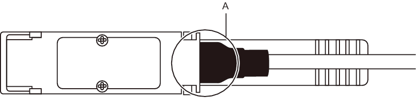
With the crossbar cables (electrical) connected to their ports, push in each cable while holding the joint (black resin part) (A in Figure 4-7) at the base of the connector of the crossbar cable (electrical).
| Note - A loose crossbar cable connection may, on rare occasions, cause an error due to poor connection. After connecting a crossbar cable, push it in again so that it is tightly in place to prevent any improper connection. Do not hold only the cable when performing work at this time. Otherwise, the cable may bend out of shape. |
|
Figure 4-7 Part to hold when checking a crossbar cable (electrical) connection
|
|
< Previous Page | Next Page >