4.3.2 Connecting crossbar cables
4.3.2 Connecting crossbar cables
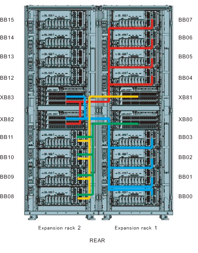
Cables that pass between racks are secured to expansion rack 2. Connect cables to their respective ports on expansion rack 1 through the empty space in the connecting part of the racks. Each cable has an attached label showing the connection destination port. Connect the cable to the port corresponding to the label.
There are two ports with the same port number. Each port on the chassis is color-coded. Connect the port to the corresponding port of the same color.
For the cable routes, see Figure 4-15.
When laying the cables, use the supplied hook-and-loop fastener strips to bundle them as appropriate.
There are two ports with the same port number. Each port on the chassis is color-coded. Connect the port to the corresponding port of the same color.
For the cable routes, see Figure 4-15.
When laying the cables, use the supplied hook-and-loop fastener strips to bundle them as appropriate.
- Unpack the cables that will pass between the racks.
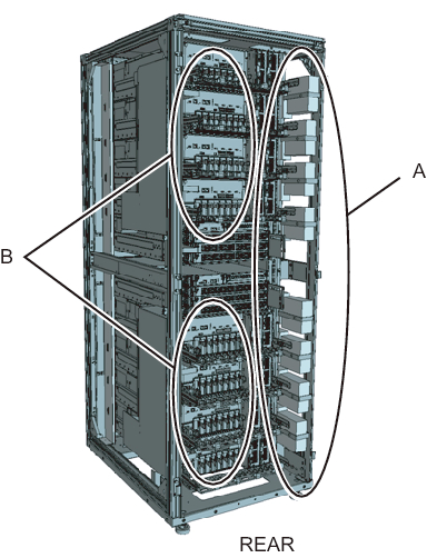
The cables are tied with hook-and-loop fastener strips, nylon ties, or the like to a side of the rack (A in Figure 4-13) or the rear of the rack (B in Figure 4-13) with their connectors wrapped in a bag.a. Remove the cable connectors from where they are secured on the rack.b. Unwrap the cable connectors.
|
Figure 4-13 Cable storage locations in expansion rack 2
|
|
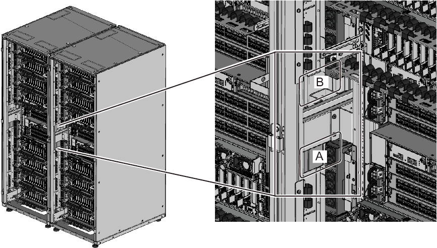
- Pass the crossbar cables (optical) unwrapped in step 1 between the upper and lower PDUs on the connecting part of the racks.
Pass the crossbar cables (optical) connecting BB#00 to BB#03 and XB#80 through the lower side of the connecting part (A in Figure 4-14).
Pass the crossbar cables (optical) connecting BB#04 to BB#07 and XB#81 through the upper side of the connecting part (B in Figure 4-14).
|
Figure 4-14 Locations for passing cables between the racks
|
|
|
Figure 4-15 Cable laying diagram
|
|
- Connect the crossbar cables (optical) to crossbar boxes.
The crossbar cables (optical) are laid in a bundle for each chassis. Connect cables without changing how they are laid.
Each cable has an attached label showing the connection destination port. Connect the cable to the port corresponding to the label. There are two ports with the same port number. Each port on the chassis is color-coded. Connect the port to the corresponding port of the same color.
Hold the connector of the crossbar cable (optical), and insert it straight into the opening. Do not hold the cable or its tab part when inserting it.
| Note - If you insert the connector with the tab pulled back, you may damage the connector. |
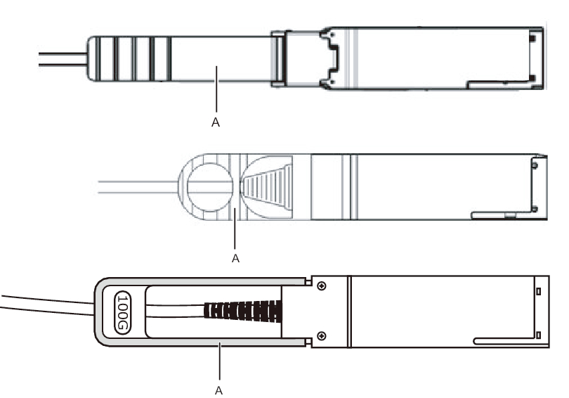
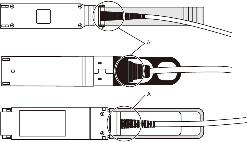
| Note - There are three types of crossbar cable (optical). Connect a crossbar cable (optical) of the same type to ports of the same port number. You can distinguish the type of crossbar cable (optical) by the tab shape (A in Figure 4-16). |
|
Figure 4-16 Crossbar cable (optical) shapes and tabs
|
|
|
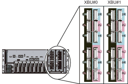
Figure 4-17 Crossbar unit port numbers (SPARC M10-4S side)
|
|
|
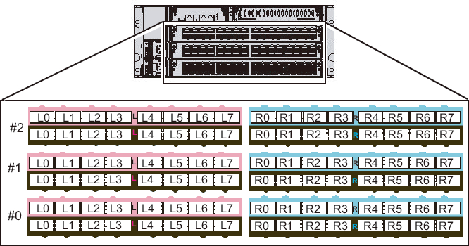
Figure 4-18 Crossbar unit port numbers (crossbar box side)
|
|
|
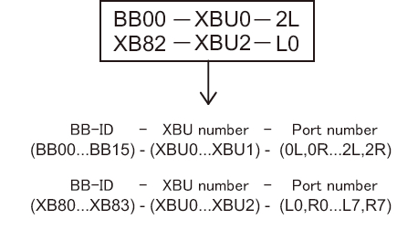
Figure 4-19 Example of the appearance of a crossbar cable label
|
|
| Note - The label shows both the cable connection destination and the unit connected by the cable. |
- Confirm that the crossbar cables (optical) are correctly and firmly connected.
With the crossbar cables (optical) connected to their ports, push in each cable while holding the joint (A in Figure 4-20) at the base of the connector of the crossbar cable (optical).
| Note - A loose crossbar cable connection may, on rare occasions, cause an error due to poor connection. After connecting a crossbar cable, push it in again so that it is tightly in place to prevent any improper connection. Do not hold only the cable when performing work at this time. Otherwise, the cable may bend out of shape. |
|
Figure 4-20 Part to hold when checking a crossbar cable (optical) connection
|
|
< Previous Page | Next Page >