5.1 Connecting Cables to the SPARC M12-2S
5.1 Connecting Cables to the SPARC M12-2S
This section describes the procedure for connecting the serial cable, network cables, and power cords to the SPARC M12-2S.
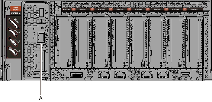
- Connect the serial cable supplied with the SPARC M12-2S from the serial port of the XSCF unit (A in Figure 5-1) to the system management terminal.
In a building block configuration, the system operates with batch operations by the master XSCF. Connect the serial cable to the master XSCF.
| Note - In a building block configuration, BB#00 is usually the master XSCF, and BB#01 is the standby XSCF. If the master is switched, BB#01 becomes the master XSCF, and BB#00 becomes the standby XSCF. |
| Note - In a building block configuration with connections through crossbar boxes, the system operates with batch operations by the master XSCF of the crossbar box. No serial cables are connected to SPARC M12-2S. |
|
Figure 5-1 Serial Port Location
|
|
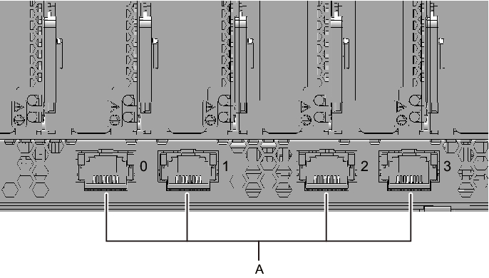
- Connect a LAN cable of Category 6 or higher from a 10 GbE LAN port (A in Figure 5-2) to the network switch or hub.
The 10 GbE LAN ports are used for the user network. These ports connect devices such as another server, another PC, and a UPS via the network switch or hub.
| Note - The SPARC M12-2S (Fujitsu Product ID SPNCCAA3xx) onboard LAN (10 GbE LAN) cannot be used. You can see the Fujitsu Product ID (SPNxxxxxxx) on the front of the SPARC M12. |
|
Figure 5-2 10 GbE LAN Port Locations
|
|
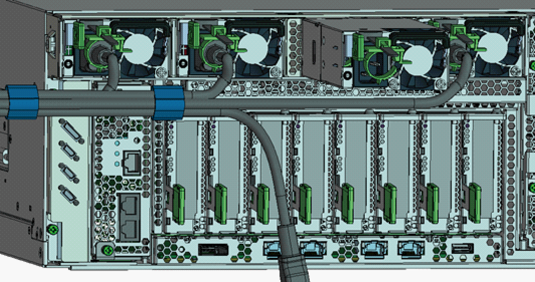
- If a PCIe card is mounted, connect a LAN cable and I/O cable to the respective ports on the PCIe card.
- Secure the cables to the cable support.
While leaving extra length, secure the cables connected to the PCIe card to the cable support. - Attach a core to each supplied power cord, and connect the cord to a power supply unit.
The work in this step differs depending on the rack where the SPARC M12-2S is mounted.
Perform the work appropriate to the rack type.
- Mounting in a general rack
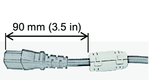
- a. Insert the power cord so that it fits into the groove of the core. Pinch the core closed until its latch is secured.
Attach the core at a location 90 mm (3.5 in) from the end of the power cord connector. (See Figure 5-3)
|
Figure 5-3 Core Attachment Location (for a General Rack)
|
|
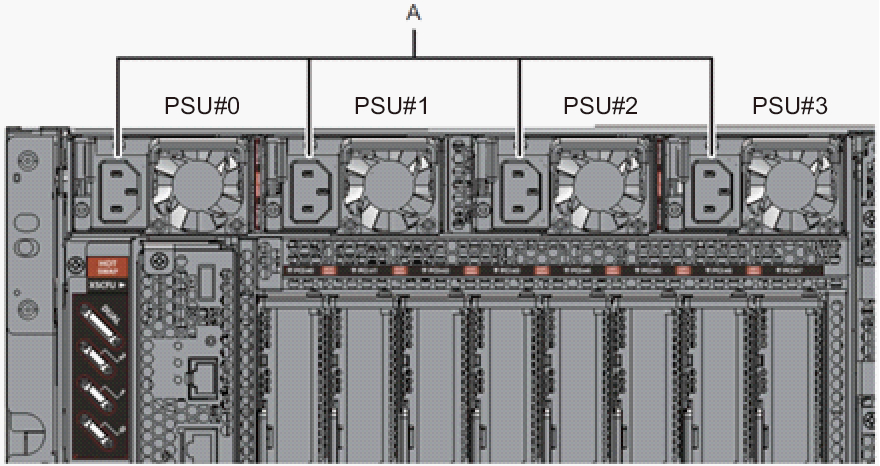
- b. Connect the power cord to the power supply unit (A in Figure 5-6).
Secure the power cord with a cable clamp.
- Mounting in an expansion rack
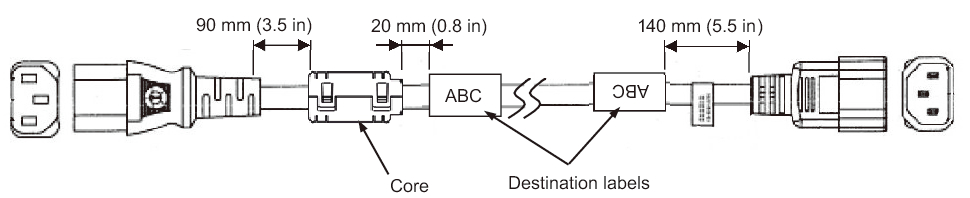
- a. Insert the power cord so that it fits into the groove of the core. Pinch the core closed until its latch is secured.
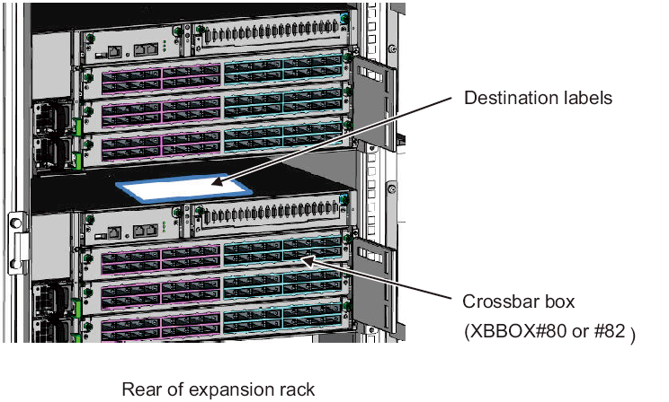
Attach the core at a location 90 mm (3.5 in) from the end of the power cord connector. (See Figure 5-4)b. Affix destination labels to the power cords.
Labels are affixed on the top panel of the crossbar box XBBOX#80 or XBBOX#82 at the rear of the expansion rack. (See Figure 5-5.)
Affix labels with the same indications to both ends of each power cord.
First affix the text part of a label to the power cord, and then wrap the label around the cord.
For the label orientation and locations for affixing the labels, see Figure 5-4.
For lists for affixing labels, see "B.6 Power Cord Connections in Expansion Racks."
|
Figure 5-4 Attached Core and Affixed Label Locations
|
|
|
Figure 5-5 Destination Label Storage Location: Top Panel of the Lower Crossbar Box
|
|
- c. Connect the power cords to the power supply units (A in Figure 5-6) according to the destination labels.
Secure the power cord with a cable clamp.
|
Figure 5-6 Power Supply Unit Locations
|
|
- Secure every power cord with a cable clamp.
Tighten the cable clamp until it holds the power cord tightly in place. ((1) in Figure 5-7)
Move the cable clamp to the base of the connector. ((2) in Figure 5-7)
|
Figure 5-7 Securing Power Cords
|

|
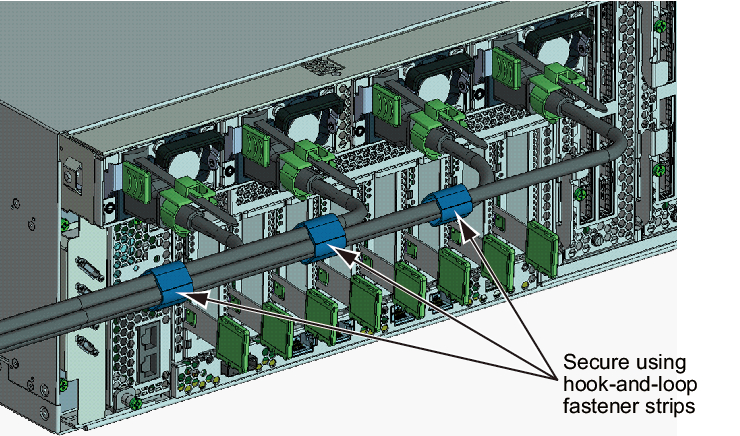
- While pulling the power cords toward the left side at the rear, gather them together, and bundle them with hook-and-loop fastener strips.
Ensure that the power cords do not hang in front of the PCIe cards under the power supply units.
|
Figure 5-8 Bundling Power Cords
|
|
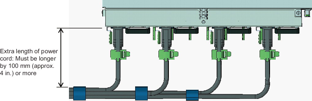
- Secure a sufficient extra length of cord from the power supply unit to the bundling point of each power cord.
In order to perform active maintenance on the power supply unit, the power cord must have the extra length.
|
Figure 5-9 Securing the Extra Length for Power Cords
|
|
|
Figure 5-10 Reference: Example of Active Maintenance of a Power Supply Unit
|
|
< Previous Page | Next Page >